Preview module and dynamic focusing laser vibrating mirror
A laser vibrating mirror and dynamic focusing technology, which is applied in optics, optical components, instruments, etc., can solve the problems of large space occupation and large light loss, and achieve the effects of small space occupation, avoiding light loss, and saving installation space
- Summary
- Abstract
- Description
- Claims
- Application Information
AI Technical Summary
Problems solved by technology
Method used
Image

Examples
Embodiment 1
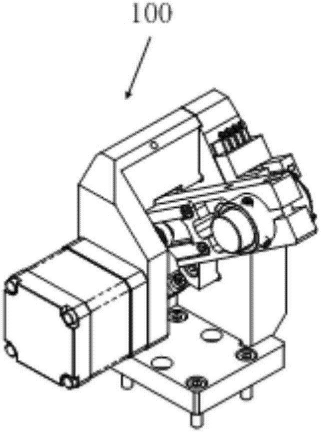
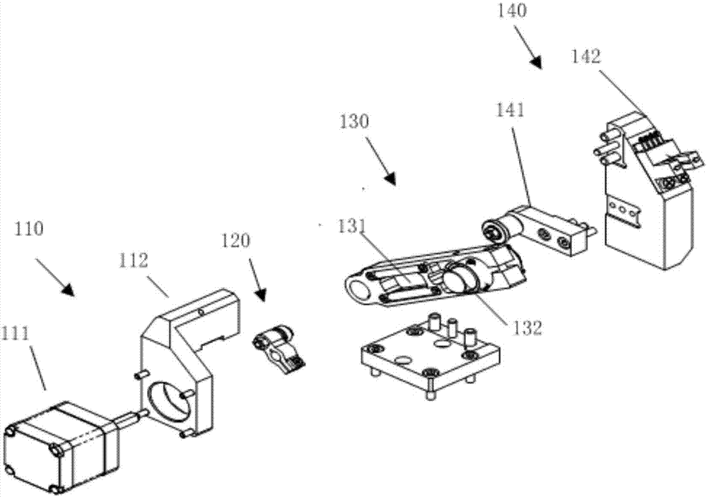
[0054] This embodiment provides a preview module 100, please refer to Figure 1 to Figure 3 , including: a first drive mechanism 110, a first transmission mechanism 120 and a rocker arm 130;
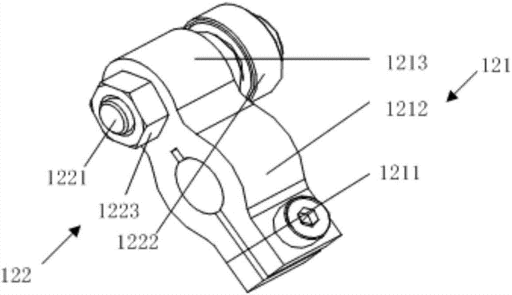
[0055] The side of the swing arm 130 is provided with a limiting groove 131, and the free end is provided with a red light emitting device 132; the first transmission mechanism 120 includes a swing rod 121 and a connecting piece 122, and the swing rod 121 is provided with a first mounting hole and a second mounting hole , the connector 122 passes through the first mounting hole and is accommodated in the limiting groove 131, the output shaft of the first driving mechanism 110 extends into the second mounting hole; the first driving mechanism 110 drives the swing rod 121 to rotate around the output shaft, and the swing rod 121 The rotation of the connecting piece 122 is driven to swing, and the swinging of the connecting piece 122 drives the rocker arm 130 to be raised or lowered.
[005...
Embodiment 2
[0066] This embodiment provides a dynamic focusing laser galvanometer, please refer to Figure 4 to Figure 7 , including the preview module 100 of Embodiment 1, and also includes a dynamic axis module 200, the dynamic axis module 200 includes a second drive mechanism 210, a second transmission mechanism 220, and a guide mechanism 230;
[0067] The second driving mechanism 210 includes a dynamic shaft driving motor 211, a dynamic shaft driving motor seat 212 for installing the dynamic shaft driving motor 211;
[0068] The second transmission mechanism 220 includes a crank 221, a first spring steel belt 222 and a second spring steel belt 223;
[0069] The crank 221 is connected to the second driving mechanism 210 through a rotating shaft, and the crank 221 is driven by the second driving mechanism 210 to rotate around the axis where the rotating shaft is located;
[0070] The first spring steel strip 222 is attached to one side of the crank 221, and the end gradually moves away...
Embodiment 3
[0089] When the conventional dynamic focus laser marking machine is used for marking different formats, the position of the dynamic axis is adjusted manually, and it needs to be returned to the factory to be opened by a professional technician to complete this work. The adjustment is difficult and the operation is cumbersome. , unable to ensure the convenience of laser on-site processing and flexible operation;
[0090] In view of the above problems, this embodiment provides a dynamic focusing laser vibrating mirror, please refer to Figure 8 with Figure 9 , including the preview module 100 in Embodiment 1, the dynamic axis module 200 in Embodiment 2, and an amplitude modulation module 300 .
[0091] The amplitude modulation module 300 includes: a connection base 310 installed under the dynamic axis module 200 , a linear guide rail 320 , and a third driving mechanism 330 for driving the connection base 310 to move along the linear guide rail 320 .
[0092] It should be note...
PUM
 Abstract
Description
Claims
Application Information
 - R&D
- Intellectual Property
- Life Sciences
- Materials
- Tech Scout
- Unparalleled Data Quality
- Higher Quality Content
- 60% Fewer Hallucinations
Browse by: Latest US Patents, China's latest patents, Technical Efficacy Thesaurus, Application Domain, Technology Topic, Popular Technical Reports.
© 2025 PatSnap. All rights reserved.Legal|Privacy policy|Modern Slavery Act Transparency Statement|Sitemap|About US| Contact US: help@patsnap.com