
The Method of Controlling Background Harmonic by Parallel Impedance Device

A technology of background harmonics and parallel connection, applied in harmonic reduction devices and AC networks to reduce harmonics/ripples, etc., can solve problems such as high cost, limited application range, and inability to suppress, and achieve simple structure and low governance cost , the effect of reducing the content

Active Publication Date: 2020-07-14
ANHUI UNIVERSITY +2
View PDF5 Cites 0 Cited by
  • Summary
  • Abstract
  • Description
  • Claims
  • Application Information

AI Technical Summary

Problems solved by technology

These two methods have different degrees of defects. APF is a single device with limited capacity and high cost. It is not suitable for direct series connection at the low-voltage outlet of distribution transformers.
The isolation transformer is usually installed on the important load feeder, and its application range is limited. It cannot be directly used at the low-voltage outlet of the distribution transformer to suppress the background harmonic voltage of the entire load bus.

Method used


Image

  • The Method of Controlling Background Harmonic by Parallel Impedance Device
  • The Method of Controlling Background Harmonic by Parallel Impedance Device
  • The Method of Controlling Background Harmonic by Parallel Impedance Device

Examples


Embodiment Construction

[0039] The following describes the technical solutions in the embodiments of the present invention clearly and completely with reference to the accompanying drawings in the embodiments of the present invention. Obviously, the described embodiments are only a part of the embodiments of the present invention, rather than all the embodiments. Based on the embodiments of the present invention, all other embodiments obtained by those of ordinary skill in the art without creative work shall fall within the protection scope of the present invention.

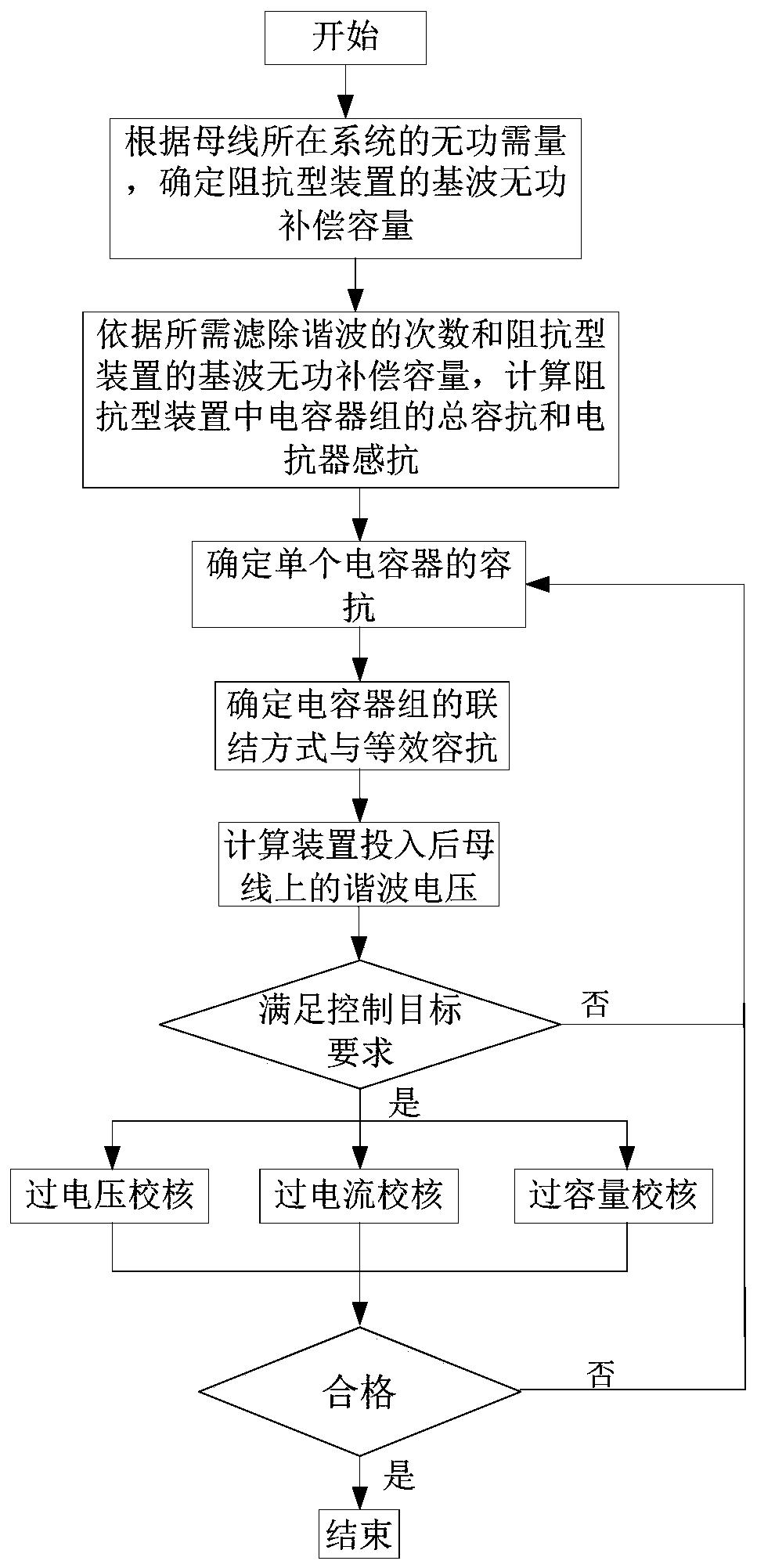
[0040] figure 1 This is a flowchart of a method for controlling background harmonics by a parallel impedance type device provided by an embodiment of the present invention. Such as figure 1 As shown, it mainly includes the following steps:

[0041] Step 1. For the bus with background harmonic control requirements and reactive power compensation requirements, determine the fundamental reactive power compensation capacity of the impedance ty...


PUM


Abstract

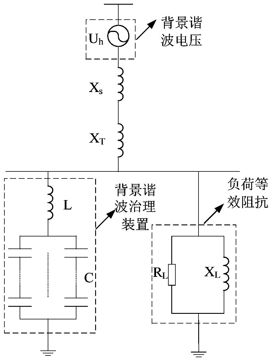
The invention discloses a method for governing a background harmonic wave by connecting an impedance type device in parallel. The method comprises the steps of: according to a reactive demand of a system where a bus is positioned, determining fundamental harmonic reactive compensation capacity of the impedance type device; according to a voltage class of the bus, determining a voltage borne by the impedance type device, and then according to required times for filtering out the harmonic wave and the fundamental harmonic reactive compensation capacity of the impedance type device, calculating a total capacitive reactance of a capacitor bank and an inductive reactance of an electric reactor in the impedance type device; determining a capacitive reactance of a single capacitor, then according to a bus voltage, the capacitive reactance of the capacitor bank and the reactive compensation capacity, determining a serial and parallel connection mode and a branch number of each capacitor in the capacitor bank so as to obtain a structure of the impedance type device; and connecting the obtained impedance type device onto the bus in parallel so as to implement government on the background harmonic wave. According to the method, content of the voltage of the background harmonic wave on the load bus can be greatly reduced, so that the adverse effect of the background harmonic wave on safe and stable operation of electric equipment under the load is reduced or improved.

Description

Technical field [0001] The present invention relates to the technical field of background harmonic control, and in particular to a method for managing background harmonics with a parallel impedance type device. Background technique [0002] With the large-scale application of new energy technologies, the installed capacity of new energy power generation such as photovoltaics has increased year by year, and the proportion of non-linear power loads has gradually increased, causing the harmonic pollution of the distribution network to gradually deteriorate. Especially in the distribution network system with distributed photovoltaic access, series-parallel resonance occurs between the inlet LCL filter of the photovoltaic inverter and the equivalent impedance of the distribution system in certain frequency ranges. The presence of background harmonics will amplify the background harmonics, causing the resonant overvoltage of the LCL filter at the entrance of the photovoltaic inverter, ...

Claims


Application Information

Patent Timeline
Patent Type & Authority Patents(China)
IPC IPC(8): H02J3/01
CPCH02J3/01Y02E40/40
Inventor 朱明星潘岩高敏高博徐斌丁津津骆晨陈洪波李冬森李运兵杨爱岭刘志敏刘春阳曾光余述良
Owner ANHUI UNIVERSITY
Learn More