Continuous internal circulation dry distillation carbonization equipment

A technology of internal circulation and dry distillation, which is applied in special forms of dry distillation, rotary carbonization furnace, indirect heating dry distillation, etc., can solve the problems of slow delivery of fuel rod combustible gas, large space in the inner cavity of the furnace, and uneven heating up and down, so as to achieve the goal of firing Good effect, good dry distillation effect, less broken charcoal effect

Active Publication Date: 2020-01-17
梧州元泓机械设备有限公司
View PDF5 Cites 0 Cited by
  • Summary
  • Abstract
  • Description
  • Claims
  • Application Information

AI Technical Summary

Problems solved by technology

[0002] Mechanism charcoal has a wide range of uses in industry, agriculture, and civil use, but the traditional charcoal firing process takes a long time and causes great pollution. Although there are several charcoal distillation equipment on the market, most of them have the following problems : 1. The furnace body is placed vertically or horizontally. Due to the uneven heating of the upper and lower sides during the firing process, it is easy to appear that the top is still raw and the bottom has been burned; 2. Due to the large amount of firing this time, the inner cavity of the furnace The space is also very large, so it is very inconvenient to place unfired fuel sticks; 3. The air pressure control in the furnace is unstable, and the combustible gas generated by the burning of the fuel sticks is transported too slowly, resulting in a high temperature for combustion with the help of the discharged combustible gas. Not enough, so that the salary stick is underburned

Method used


Image

  • Continuous internal circulation dry distillation carbonization equipment
  • Continuous internal circulation dry distillation carbonization equipment
  • Continuous internal circulation dry distillation carbonization equipment

Examples


Embodiment Construction

[0030] The present invention will be further described in detail below in conjunction with the accompanying drawings, so that those skilled in the art can implement it with reference to the description.

[0031] It should be noted that, in the description of the present invention, the terms "horizontal", "vertical", "upper", "lower", "front", "rear", "left", "right", "vertical", The orientation or positional relationship indicated by "horizontal", "top", "bottom", "inner", "outer", etc. is based on the orientation or positional relationship shown in the drawings, and is only for the convenience of describing the present invention and simplifying the description, and It is not to indicate or imply that the device or element referred to must have a particular orientation, be constructed in a particular orientation, or operate in a particular orientation, and thus should not be construed as limiting the invention.

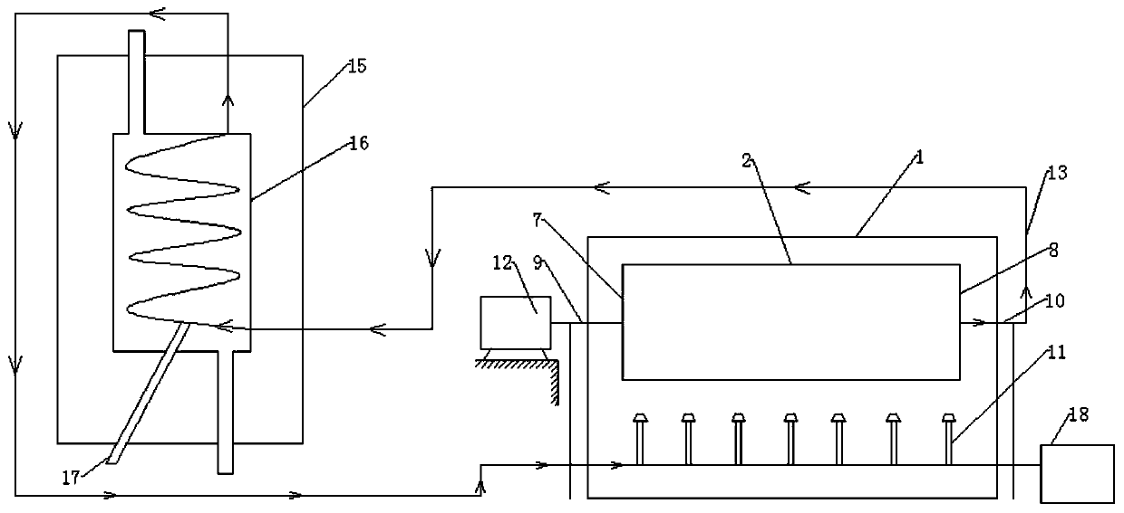
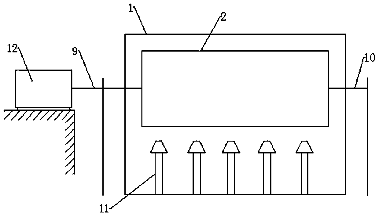
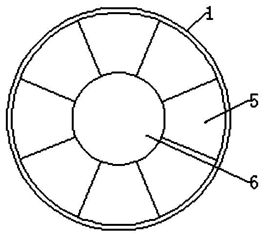
[0032] Such as Figure 1 to Figure 5 As shown, the present inve...


PUM


Abstract

The invention discloses continuous inner-cycle dry distillation and carbonization equipment. The equipment comprises a combustion reaction chamber and a dry distillation kettle, wherein the combustion reaction chamber is hollow; the dry distillation kettle is a cylindrical column and is horizontally arranged in the combustion reaction chamber, a plurality of shin plates are arranged on the inner wall of the dry distillation kettle, rig plates are vertically arranged on two side plate surfaces of the shin plates, a first charcoal bin placed on the rig plates is arranged between each two adjacent shin plates, all the first charcoal bins form a circle coaxial with the dry distillation kettle, and meanwhile, second charcoal bins matched with the first charcoal bins are arranged in the circle; and a detachable first sealing cover and a detachable second sealing cover are respectively arranged at two ends of the dry distillation kettle, a rotating shaft is coaxially arranged at the outer end of the first sealing cover, and a flue is coaxially formed in the outer end of the second sealing cover and is communicated to the inside of the dry distillation kettle. The continuous inner-cycle dry distillation and carbonization equipment has the characteristics that the sintering time is saved, the uniform dry distillation and carbonization in a furnace body are realized, and the fetching and placement of an operator are facilitated.

Description

technical field [0001] The invention relates to the field of charcoal carbonization. More specifically, the present invention relates to a continuous internal circulation dry distillation and carbonization equipment. Background technique [0002] Mechanism charcoal has a wide range of uses in industry, agriculture, and civil use, but the traditional charcoal firing process takes a long time and causes great pollution. Although there are several charcoal distillation equipment on the market, most of them have the following problems : 1. The furnace body is placed vertically or horizontally. Due to the uneven heating of the upper and lower sides during the firing process, it is easy to appear that the top is still raw and the bottom has been burned; 2. Due to the large amount of firing this time, the inner cavity of the furnace The space is also very large, so it is very inconvenient to place unfired fuel sticks; 3. The air pressure control in the furnace is unstable, and the...

Claims


Application Information

Patent Timeline
Patent Type & Authority Patents(China)
IPC IPC(8): C10B1/10C10B53/02C10B47/30C10B57/00
CPCC10B1/10C10B47/30C10B53/02C10B57/00Y02E50/10
Inventor 陈阵
Owner 梧州元泓机械设备有限公司
Why Eureka
Try Eureka