Flame-ejecting sparking plug and internal combustion engine and automobile therewith
A technology for spark plugs and internal combustion engines, which is applied to spark plugs, electrical components, circuits, etc., can solve the problems of complex fuel supply systems and increased costs, and achieve the effects of improving thermal power conversion efficiency, thermal efficiency, and ignition intensity.
- Summary
- Abstract
- Description
- Claims
- Application Information
AI Technical Summary
Problems solved by technology
Method used
Image
Examples
Embodiment 1
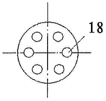
[0086] Embodiment 1: The parameters of a typical flame-injecting spark plug are Figure 3A and Figure 3B For example, Figure 3AThe effective volume in the semi-closed cavity 21 shown is 0.6 cubic centimeters. The number of spray holes on the end surface is 7 (including 1 central spray hole 24), and the hole shape is circular. The injection angle of the central injection hole 24 is zero. The radial injection angles of the other six end face spray holes 18 are 30 degrees, and the oblique angles in the circumferential direction are 20 degrees. The total area of the end surface nozzle hole 18 and the center nozzle hole 24 is 25% of the circular cross-sectional area of the inner volume of the cavity (corresponding to the end surface). The number of side spray holes 17 is 2, symmetrically distributed, the hole shape is circular, and the aperture is 2 / 3 of the end face spray holes. The radial injection angle of the side spray holes 17 is 45 degrees, and the circumferential ...
Embodiment 2
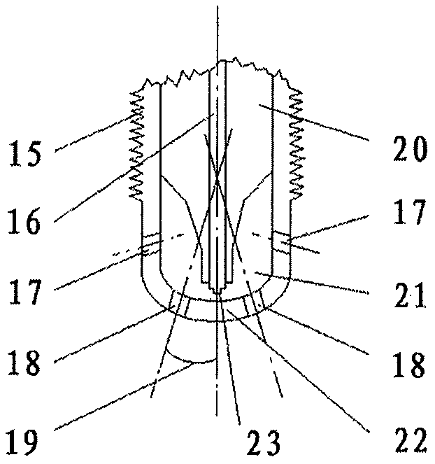
[0088] Example 2, Figure 2A The central electrode 23 is hidden inside the housing 22 of the semi-closed cavity 21, which is the same as the semi-exposed and semi-exposed central electrode 23 of Fig. 3A Figure 4A Compared with the bare center electrode 23, the direct ignition of the combustible gas in the combustion chamber by the electrode spark is avoided. The ignition action is divided into two parts, one is that the electrode spark ignites the combustible gas in the semi-closed cavity 21, and the other is that the combustible gas in the semi-closed cavity 21 burns and ejects out of the semi-closed cavity 21, which has an impact on the combustion chamber and the cylinder. Combustible gases in the fire are ignited. Like this, the time interval that combustible gas is ignited at the top and the bottom of the combustion chamber and even the depth of the cylinder is shortened. The disadvantage is that the combustible gas concentration near the electrode is greatly affected b...
Embodiment 3
[0089] Example 3, Figure 4A In the shown spark plug, the position of the positive and negative electrodes (23 and 22) is at the edge of the junction between the semi-closed cavity 21 and the combustion chamber (this edge just happens to be the gap position between the positive and negative electrodes, and it is also the position of the annular injection hole 26. Position), exposed outside the semi-closed cavity 21, the combustible gas concentration and air-fuel ratio around the electrode are the same as most areas of the combustion chamber, the reliability of electrode ignition is hardly affected by the diffusion of combustible gas into the semi-closed cavity 21 Impact. In addition to being suitable for general internal combustion engine ignition requirements, this spark plug is more suitable as an ignition device for a lean-burn engine, such as an ignition device for a homogeneous compression ignition gasoline engine (HCCI).
[0090] When the homogeneous compression ignitio...
PUM
 Abstract
Description
Claims
Application Information
 - R&D
- Intellectual Property
- Life Sciences
- Materials
- Tech Scout
- Unparalleled Data Quality
- Higher Quality Content
- 60% Fewer Hallucinations
Browse by: Latest US Patents, China's latest patents, Technical Efficacy Thesaurus, Application Domain, Technology Topic, Popular Technical Reports.
© 2025 PatSnap. All rights reserved.Legal|Privacy policy|Modern Slavery Act Transparency Statement|Sitemap|About US| Contact US: help@patsnap.com


