
Vortex solid-liquid separator

A solid-liquid separator, eddy current technology, applied in filtration separation, separation methods, water/sludge/sewage treatment, etc., can solve the problems of low discharge efficiency, high equipment cost, complex structure, etc., to improve discharge efficiency and shorten the time. The effect of discharging stroke and improving work efficiency

Pending Publication Date: 2017-11-10
象山德曼机械有限公司
View PDF5 Cites 1 Cited by
  • Summary
  • Abstract
  • Description
  • Claims
  • Application Information

AI Technical Summary

Problems solved by technology

[0004] This structure improves the dehydration degree of the discharged dewatered filter cake and improves the dehydration efficiency, but there are the following technical problems at the same time. 1. The compression filter is composed of a C-shaped annular part and a straight part, and the straight part protrudes from the C The word-shaped annular part makes the whole structure larger and more complicated, which increases the difficulty of processing and the cost of the whole equipment is higher; 2. The existence of the straight part prolongs the discharge stroke of the filter cake, which makes the filter cake unable to Flexible, fast and convenient discharge, the filter cake discharge time is longer, and the discharge efficiency is low

Method used


Image

  • Vortex solid-liquid separator
  • Vortex solid-liquid separator
  • Vortex solid-liquid separator

Examples


Embodiment Construction

[0035] The following are specific embodiments of the present invention and in conjunction with the accompanying drawings, the technical solutions of the present invention are further described, but the present invention is not limited to these embodiments.

[0036] The present invention improves the traditional compression filter with the purpose of simplifying the structure of the entire solid-liquid separator, reducing its processing difficulty, reducing production costs, shortening the discharge stroke of the filter cake, and improving the discharge efficiency of the filter cake, so as to improve the solid-liquid separator. The market utilization rate of the separator gradually expands the scope of environmental protection.

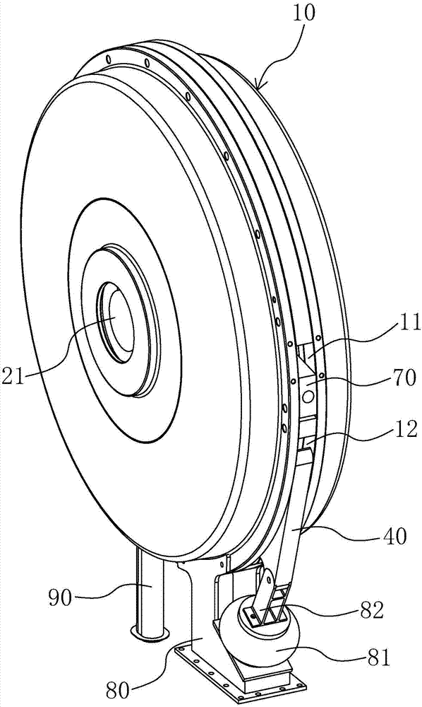
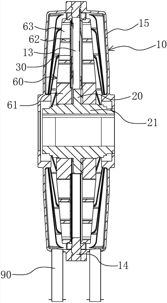
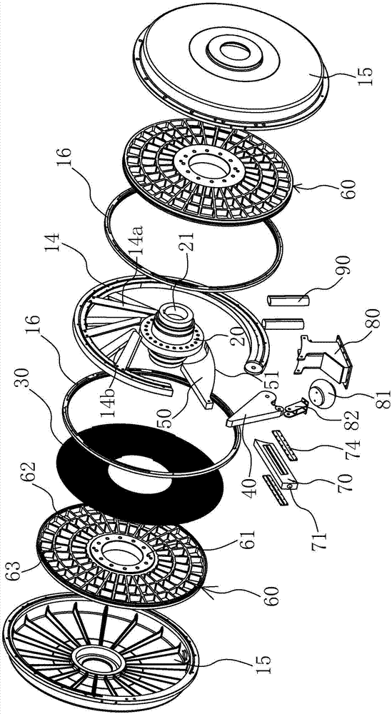
[0037] Such as Figure 1 to Figure 3 As shown, a vortex solid-liquid separator of the present invention includes a casing 10, an inner ferrule 20, a filter screen 30 and a back pressure plate 40.

[0038] The casing 10 is an upright circular flat holl...


PUM


Abstract

The invention provides a vortex solid-liquid separator, belongs to the technical field of dewatering equipment and solves the technical problems of complicated structure, inconvenient processing and high cost of filters in the prior art; a vortex solid-liquid separator, the vortex solid-liquid separator comprises a casing, an inner sleeve ring, filter nets, a filter chamber and a back pressure plate, the casing is an internal empty hollow structure, the casing is provided with a liquid inlet and a slag discharge port which are separated, the inner sleeve ring is arranged in the casing, and is movably connected with the casing; the two pieces of filter nets are arranged in the casing, the two pieces of filter nets are separated and fixedly connected with the inner sleeve ring; the filter chamber is formed in the casing, the inner sleeve ring and the filter nets, the filter chamber is communicated with the liquid inlet and the slag discharge port, the back pressure plate is arranged at the slag discharge port, and is movably connected with the bottom of the casing, the back pressure plate can rotate relative to the casing, the inner sleeve ring can rotate according to the direction from the liquid inlet to the slag discharge port, the filter nets can rotate synchronously with the inner sleeve ring, a linear part of a traditional structure is omitted, and the vortex solid-liquid separator is relatively small in volume, simple in processing and relatively low in production cost.

Description

technical field [0001] The invention belongs to the technical field of dehydration equipment, and relates to a separator, in particular to a vortex solid-liquid separator which adopts vortex technology to separate solid and liquid. Background technique [0002] The solid-liquid separation device is a compression filter device used to compress and dehydrate the raw materials or semi-processed products of processed food, or sludge and other hydrated substances. It is more commonly used for sewage treatment to achieve the purpose of environmental protection. [0003] Traditional solid-liquid separators include various types of devices such as centrifugal separators, centrifugal filters, pressure filters, screw presses, rotary vacuum filters, and rotary compression filters. Among them, the authorized announcement number is CN 1199705C The invention patent provides a rotary compression filter for sludge dewatering, which includes a filter chamber with a rectangular cross-section;...

Claims


Application Information

Patent Timeline
IPC IPC(8): B01D33/17C02F11/12B01D33/39
CPCB01D33/17B01D33/39C02F11/12C02F11/121
Inventor 毛克峰
Owner 象山德曼机械有限公司
Learn More