Laser scanning and heating fusion splicing mechanism of optical fiber fusion splicer

An optical fiber fusion splicer and laser scanning technology, applied in the field of optical fiber fusion, can solve the problems of tediousness, poor fusion effect, and low success rate

Inactive Publication Date: 2017-11-10
NANJING JILONG OPTICAL COMM
View PDF4 Cites 0 Cited by
  • Summary
  • Abstract
  • Description
  • Claims
  • Application Information

AI Technical Summary

Problems solved by technology

This method is extremely cumbersome, each fiber requires a large amount of experi

Method used


Image

  • Laser scanning and heating fusion splicing mechanism of optical fiber fusion splicer

Examples


Embodiment Construction

[0010] Embodiments of the present invention are described in detail below in conjunction with the accompanying drawings:

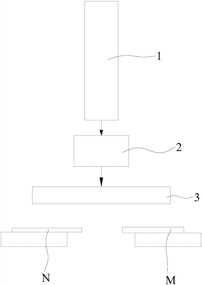
[0011] Optical fiber fusion machine laser scanning heating fusion mechanism, such as figure 1 As shown, it includes a carbon dioxide laser 1, the laser output port of the carbon dioxide laser 1 is equipped with a vibrating mirror 2, and the front end of the vibrating mirror 2 is installed with a field mirror 3, and the laser beam emitted by the carbon dioxide laser 1 is scanned by the vibrating mirror 2 and focused by the field mirror 3 to form Laser spot output.

[0012] The carbon dioxide laser 1 of the present invention is installed on the optical fiber fusion splicer to replace the heat source (arc) of the existing optical fiber fusion splicer, and the vibrating mirror 2 and the field mirror 3 are installed at the laser output port of the carbon dioxide laser 1 . The fiber fusion splicing process is as follows: first, clamp the two sections of optical...


PUM


Abstract

The invention discloses a laser scanning and heating fusion splicing mechanism of an optical fiber fusion splicer for the fusion splicing of optical fibers different in material and core-diameter. The laser scanning and heating fusion splicing mechanism comprises a laser unit. The laser output port of the laser unit is provided with a galvanometer. The front end of the galvanometer is provided with a field lens. A laser beam emitted by the laser unit is subjected to the scanning of the galvanometer and the focusing of the field lens to form laser light spots and then the laser light spots are outputted. According to the technical scheme of the invention, the laser unit is used as a fusion splicing heat source, and the galvanometer and the field lens are used for outputting, scanning and focusing the laser. The step-by-step fusion splicing of optical fibers different in material and core-diameter is realized through controlling the laser output power and the field lens. Therefore, the synchronous softening of the optical fibers is achieved. The laser scanning and heating fusion splicing mechanism has the advantages of rapid fusion splicing, good fusion splicing effect and the like.

Description

technical field [0001] The invention relates to the field of optical fiber welding, in particular to a laser scanning heating welding mechanism of an optical fiber welding machine suitable for welding optical fibers of different materials and different core diameters. Background technique [0002] With the continuous development of optical communication and optoelectronic technology, various new types of optical fibers and optical fibers with different core diameters have been continuously developed, and a big problem that follows is the connection between these optical fibers of different thicknesses and different materials. At present, the following two connection methods are basically used in the industry: [0003] 1. Cold splicing: use ceramic ferrules and sleeves to align and fix optical fibers of different materials through a mechanical structure. This method has large insertion loss and poor return loss, is expensive, and has poor connection effect. There is an inter...

Claims


Application Information

Patent Timeline
IPC IPC(8): G02B6/255
CPCG02B6/2551
Inventor 吴超王传兵居兰
Owner NANJING JILONG OPTICAL COMM
Why Eureka
Try Eureka