Multi-tenant network optimization method and system, computer device and memory medium

A network system and network optimization technology, applied in the field of cloud computing, can solve problems such as self-service network network performance bottlenecks, high network performance requirements, and no support for tenants to create virtual private clouds. The effect of performance requirements

Inactive Publication Date: 2017-11-10
CHINANETCENT TECH
View PDF4 Cites 21 Cited by
  • Summary
  • Abstract
  • Description
  • Claims
  • Application Information

AI Technical Summary

Problems solved by technology

[0003] Please refer to figure 1 , which is the existing self-service network architecture. Although the self-service network has rich functions and can customize the virtual private cloud (Virtual Private Cloud, VPC), but because the network ingress and egress traffic of all tenants’ virtual machines (Virtual Machine, VM) needs to Through the virtual router (Virtual Router), the virtual router is concentrated on the network node, and the virtual router finally sends or receives the data packet through the physical network card of the network node, so the network performance is limited by the network card bottleneck of the network node, and the self-service network exists network Performance bottleneck, not suitable for tenants with high network performance requirements
[0004] Please refer to figure 2 , for the existing provider network architecture, the inbound and outbound traffic does not need to pass through the virtual router on the network node, but the provider network itself does not support tenants to create a virtual private cloud, that is, all virtual machines under the same tenant cannot be formed into a private cloud
[0005] To sum up, the existing network cannot combine the advantages of self-service network and supplier network in a multi-tenant environment, so as to achieve both high network performance requirements and customizable private cloud creation

Method used


Image

  • Multi-tenant network optimization method and system, computer device and memory medium
  • Multi-tenant network optimization method and system, computer device and memory medium
  • Multi-tenant network optimization method and system, computer device and memory medium

Examples


no. 1 example

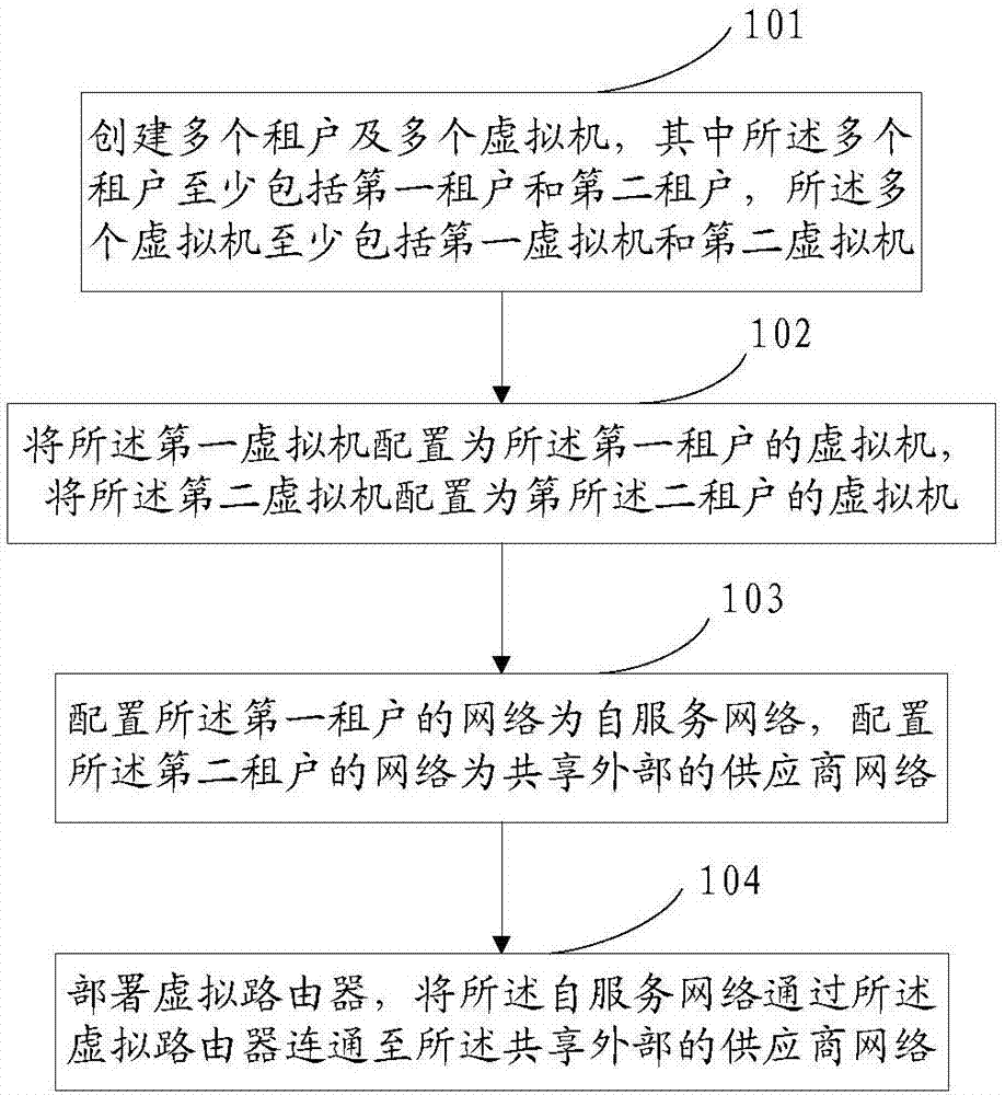
[0064] see image 3 As shown, the first embodiment of the present invention provides a multi-tenant network optimization method, including steps 101 to 104, which are described in detail as follows.

[0065] Step 101: Create multiple virtual machines and multiple tenants, wherein the multiple tenants include at least a first tenant and a second tenant, and the multiple virtual machines include at least a first virtual machine and a second virtual machine.

[0066] Wherein, since multiple virtual machines are encapsulated in different broadcast domains, multiple virtual machines share hardware resources without interfering with each other, the IP addresses of virtual machines of different tenants may be the same, but the IP addresses of virtual machines of the same tenant are different.

[0067] Step 102: Configure the first virtual machine as a virtual machine of the first tenant, and configure the second virtual machine as a virtual machine of the second tenant.

[0068] Amo...

no. 2 example

[0076] see Figure 5 As shown, the second embodiment of the present invention provides a flow chart of specific steps for creating multiple virtual machines, which includes steps 201 to 212, which are described in detail as follows.

[0077] Step 201: Receive a virtual machine creation request.

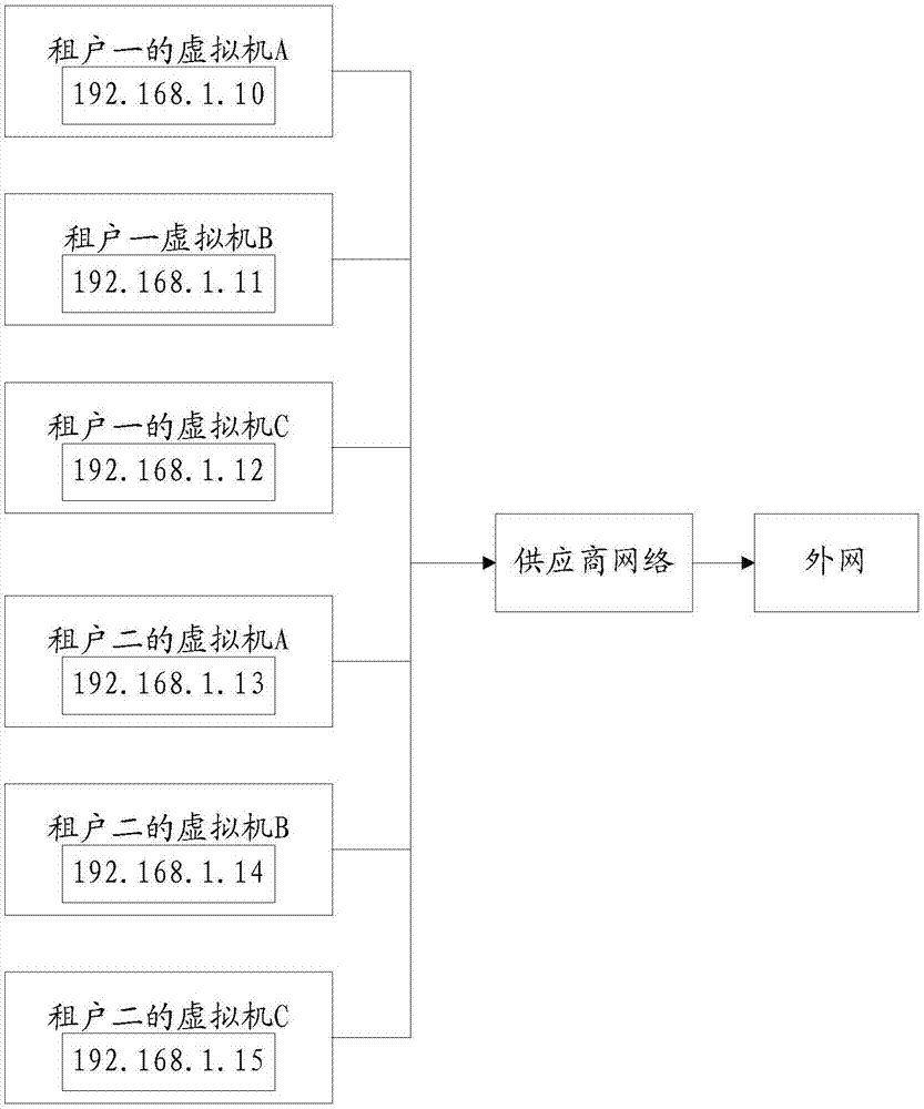
[0078] Step 202: Determine whether to use the provider network.

[0079] Specifically, it is judged whether to use the provider network, if not, go to step 203, and if yes, go to step 204.

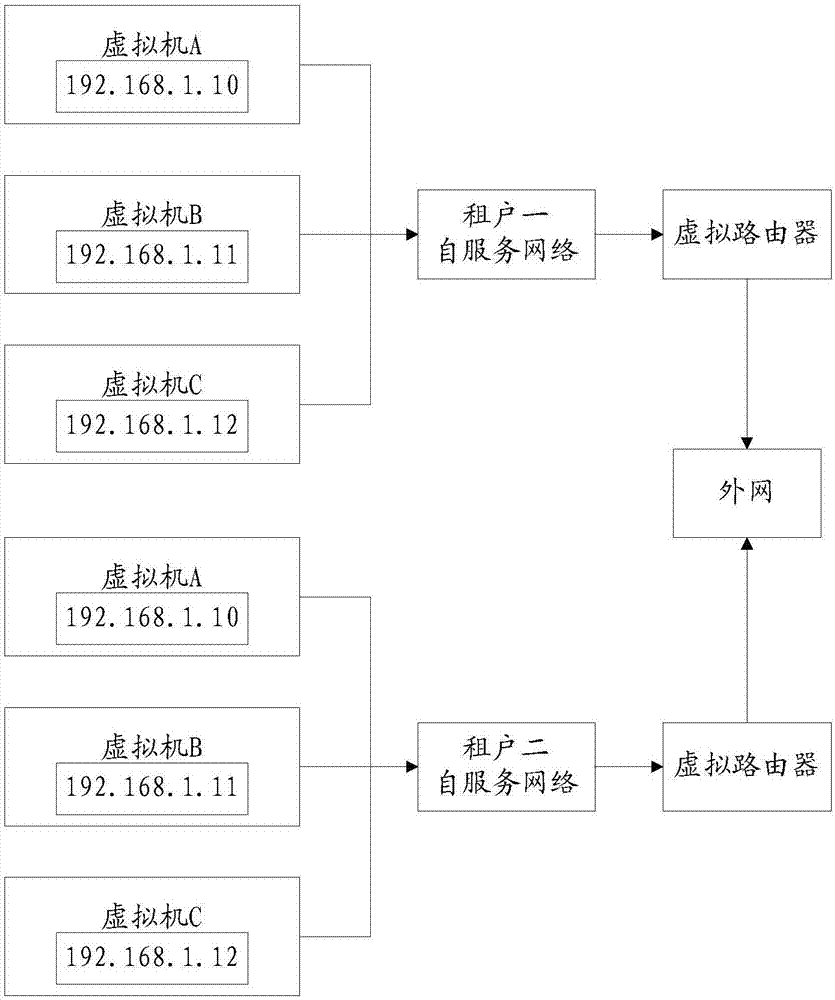
[0080] Step 203: Create or obtain a virtual router of the self-service network, create a virtual machine, and associate the virtual router with the virtual machine.

[0081] Specifically, a self-service network is created through an intranet IP; a network node is created or a virtual router is obtained; a computing node creates a virtual machine; and the virtual router and the virtual machine are associated to realize network connection.

[0082] Step 204: judging whether to use the public netw...

no. 3 example

[0100] see Image 6 As shown, the third embodiment of the present invention provides a multi-tenant network optimization system, and image 3 The shown multi-tenant network optimization method corresponds to the details of the multi-tenant network optimization method in the first embodiment, and achieves the same effect. The multi-tenant network optimization system 30 includes:

[0101] Creating module 31: used to create multiple virtual machines and multiple tenants, wherein the multiple tenants include at least a first tenant and a second tenant, and the multiple virtual machines include at least a first virtual machine and a second virtual machine.

[0102] Wherein, since multiple virtual machines are encapsulated in different broadcast domains, multiple virtual machines share hardware resources without interfering with each other, the IP addresses of virtual machines of different tenants may be the same, but the IP addresses of virtual machines of the same tenant are diff...


PUM


Abstract

The invention provides a multi-tenant network optimization method. The method comprises the steps of establishing a plurality of virtual machines and a plurality of tenants, wherein the plurality of tenants at least comprise a first tenant and a second tenant, and the plurality of virtual machines at least comprises a first virtual machine and a second virtual machine; configuring the first virtual machine as the virtual machine of the first tenant, configuring the second virtual machine as the virtual machine of the second tenant; configuring a network of the first tenant as a self-service network and configuring the network of the tenant as a shared external supplier network; and deploying a virtual router and carrying out connection on the self-service network and the shared external supplier network through the virtual router. Personalized setting demands of the tenants for a private cloud are satisfied and the demands of the tenants for the network performance are improved. The invention also discloses a multi-tenant network optimization system, a computer device and a memory medium.

Description

technical field [0001] The present invention relates to the technical field of cloud computing, in particular to a multi-tenant network optimization method and system, computing equipment, and computer storage media. Background technique [0002] With the development of cloud computing, data center virtualization has become a trend. The private cloud service project is mainly used to solve multi-data center resource virtualization and improve resource utilization. The project is developed based on the open source cloud platform OpenStack. At present, the common multi-tenant network architecture of OpenStack is the self-service network (Self-service network). [0003] Please refer to figure 1 , which is the existing self-service network architecture. Although the self-service network has rich functions and can customize the virtual private cloud (Virtual Private Cloud, VPC), but because the network ingress and egress traffic of all tenants’ virtual machines (Virtual Machine,...

Claims


Application Information

Patent Timeline
Patent Type & Authority Applications(China)
IPC IPC(8): H04L12/24H04L12/741H04L12/851H04L12/931H04L12/46H04L45/74
CPCH04L12/4633H04L41/00H04L41/0823H04L41/5025H04L45/74H04L47/24H04L49/208
Inventor 周国美陈进贤刘泽军许鹏耀
Owner CHINANETCENT TECH
Why Eureka
Try Eureka