Permanent magnet brushless DC motor driver control method
A permanent magnet brushless DC and motor driver technology, which is applied in the direction of motor generator control, electronic commutation motor control, electromechanical brake control, etc. System anti-interference ability and other issues, achieve good control accuracy and dynamic response performance, improve anti-interference ability, and solve the contradiction between overshoot and rapidity
- Summary
- Abstract
- Description
- Claims
- Application Information
AI Technical Summary
Problems solved by technology
Method used
Image
Examples
Embodiment 1
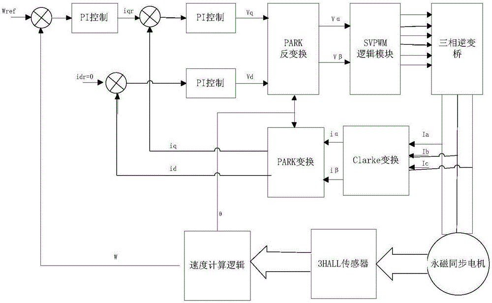
[0075] As shown in the figure, the permanent magnet brushless DC motor driver control method provided in this embodiment, the permanent magnet brushless DC motor driver includes a processor DSP, a HALL sensor, a DC motor, a PID controller, a PARK conversion module, and a PARK inverter. Transformation module, three-phase inverter, Clark transformation module, speed calculation logic module:
[0076] The driver of this embodiment uses a serial port or a resistive memory motor to adjust the speed, and directly sends the control command to a DSP, and uses the timer of the DSP to use the PWM comparison output mode to output 3 groups of independent complementary PWM signals. The motor phase current sampling module directly inputs the current sampling voltage signal to the ADC pin of the DSP, and the CPU obtains the corresponding sampling value. After conversion by the internal software, the PID controller, the PARK conversion module, and the PARK inverse conversion module are convert...
Embodiment 2
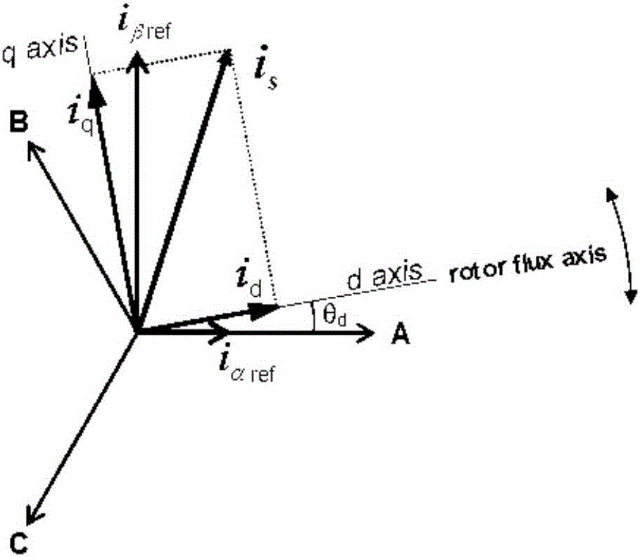
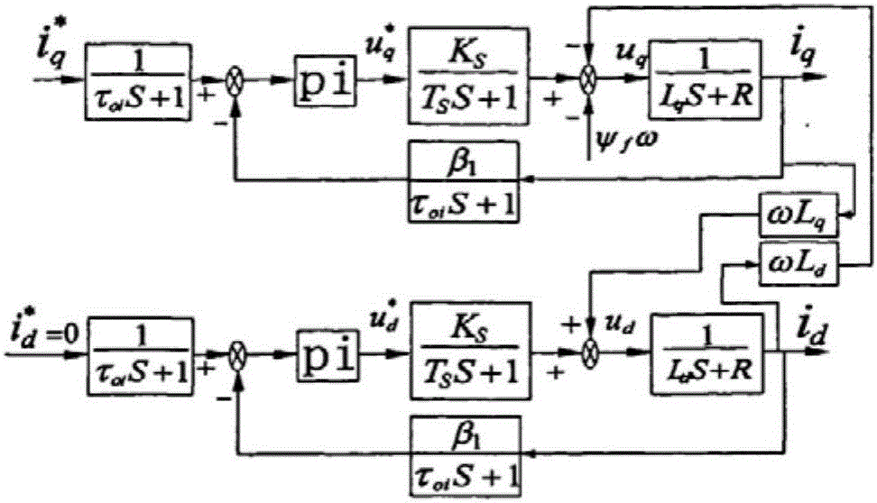
[0118] The basic idea of the FOC control algorithm used in this embodiment is to decompose the current vector into two mutually perpendicular and independent vectors i on the magnetic field orientation coordinates d (the excitation current component that produces the magnetic flux) and i q (Torque current component that produces torque) Control i d and i q The torque of the motor can be controlled. Control method according to rotor flux orientation (i d =0) make the stator current vector on the q-axis without d-axis component. At this moment the torque T e and i q linear relationship. Therefore, just for i q Controlling can achieve the purpose of controlling torque. Clark transformation is the coordinate transformation of the stator three-phase winding from the stationary ABC axis system to the stationary αβ axis system. Park transformation means that the two-phase stationary coordinates are equivalent to the two-phase rotating coordinates through the transformation ...
PUM
 Abstract
Description
Claims
Application Information
 - R&D
- Intellectual Property
- Life Sciences
- Materials
- Tech Scout
- Unparalleled Data Quality
- Higher Quality Content
- 60% Fewer Hallucinations
Browse by: Latest US Patents, China's latest patents, Technical Efficacy Thesaurus, Application Domain, Technology Topic, Popular Technical Reports.
© 2025 PatSnap. All rights reserved.Legal|Privacy policy|Modern Slavery Act Transparency Statement|Sitemap|About US| Contact US: help@patsnap.com


