
Rotary milling and planing tool bit

A milling cutter, rotary technology, applied in the direction of milling cutter, milling machine equipment, manufacturing tools, etc., to achieve the effect of easy disassembly and improved efficiency

Inactive Publication Date: 2017-11-14
JIANGSU HENGLI MACHINE TOOL
View PDF0 Cites 4 Cited by
  • Summary
  • Abstract
  • Description
  • Claims
  • Application Information

AI Technical Summary

Problems solved by technology

[0003] The technical problem to be solved by the present invention is: to overcome the technical problem of the milling rate of the steel plate surface in the prior art, and to provide a rotary milling cutter head

Method used


Image

  • Rotary milling and planing tool bit

Examples


Embodiment Construction

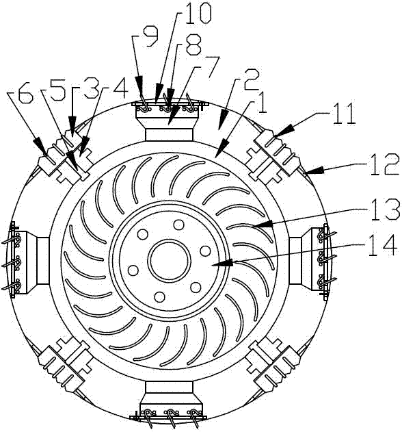
[0019] The present invention is described in further detail now in conjunction with accompanying drawing. These drawings are all simplified schematic diagrams, which only illustrate the basic structure of the present invention in a schematic manner, so they only show the configurations related to the present invention.

[0020] Such as figure 1 As shown, the present invention is a rotary milling cutter head, including a tray and an ash discharger, wherein an annular connecting ring is arranged on the tray, and a milling cutter and an ash discharger are arranged in an annular array on the connecting ring. chip cutter; wherein the milling cutter includes a milling block, the milling block is connected to the connection ring through a height adjustment mechanism, and the height adjustment mechanism includes a support block embedded in the connection ring, and the support block is connected with A push screw, an inlay groove for inlaying milling blocks is arranged in the connecti...


PUM


Abstract

The invention relates to a rotary milling cutter head, which includes a tray and an ash discharger. An annular connecting ring is arranged on the tray, and a milling cutter and a chip removal cutter are arranged in an annular array on the connecting ring; the milling cutter includes a milling cutter There are a number of prismatic cutting protrusions in a linear array on the milling block, and buffer grooves are processed at the positions between the corresponding cutting protrusions on the milling block; the chip removal knife is installed in the drain hole that runs through the connecting ring , the chip removal knife includes several pieces of elastic blades, the elastic blades are fixed on the outer edge of the connecting ring corresponding to the discharge hole through the connecting seat, the axis of the elastic blade is inclined to the radial axis of the connecting ring, and a chip removal blade is provided between the chip removal knives Gap; the ash discharger includes ash discharge impeller, on which a circular array is provided with several arc-shaped impeller blades, a diversion cover is also provided on the ash discharge impeller, and a discharge port is arranged in the middle of the ash discharge cover. The middle part of the ash discharge impeller is rotatably connected with the middle part of the tray through a bearing, and an inertia block is also fixedly connected with the middle part of the ash discharge impeller.

Description

technical field [0001] The invention relates to a milling cutter used for chip removal on the surface of a steel plate, in particular to a rotary milling cutter head. Background technique [0002] Before the steel plate is finished, it is generally necessary to remove the oxide layer and initially polish the surface on a milling machine. There are generally two methods for this removal. One is to directly mill the surface of the steel plate with a milling cutter. This method has a better surface finish. , the secondary processing degree is relatively low, but the feeding speed of the milling cutter is relatively low, and the grinding rate is slow; the other is to grind the surface by grinding the tool. The debris is easy to cause secondary damage to the surface of the steel plate, and the surface flatness obtained after grinding is poor, and it takes multiple times of grinding to obtain the required surface, and the rate is also low. Contents of the invention [0003] The...

Claims


Application Information

Patent Timeline
Patent Type & Authority Applications(China)
IPC IPC(8): B23C5/16B23C5/20
CPCB23C5/165B23C5/20
Inventor 仲秋徐俊孙德洲韩海群
Owner JIANGSU HENGLI MACHINE TOOL
Learn More