Method and system for engine control

An engine, engine torque technology, applied in engine control, road vehicle drive control system, machine/engine, etc., can solve problems such as runout, and achieve the effect of reducing compression ratio and fuel economy loss

Active Publication Date: 2022-01-14
FORD GLOBAL TECH LLC
View PDF17 Cites 0 Cited by
  • Summary
  • Abstract
  • Description
  • Claims
  • Application Information

AI Technical Summary

Problems solved by technology

Another problem associated with frequent engine pull-ups and pull-downs is that when the engine passes through a low speed range (eg, between 300rpm-500rpm) bobble can occur

Method used


Image

  • Method and system for engine control
  • Method and system for engine control
  • Method and system for engine control

Examples


Embodiment Construction

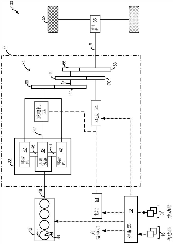
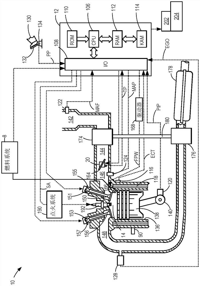
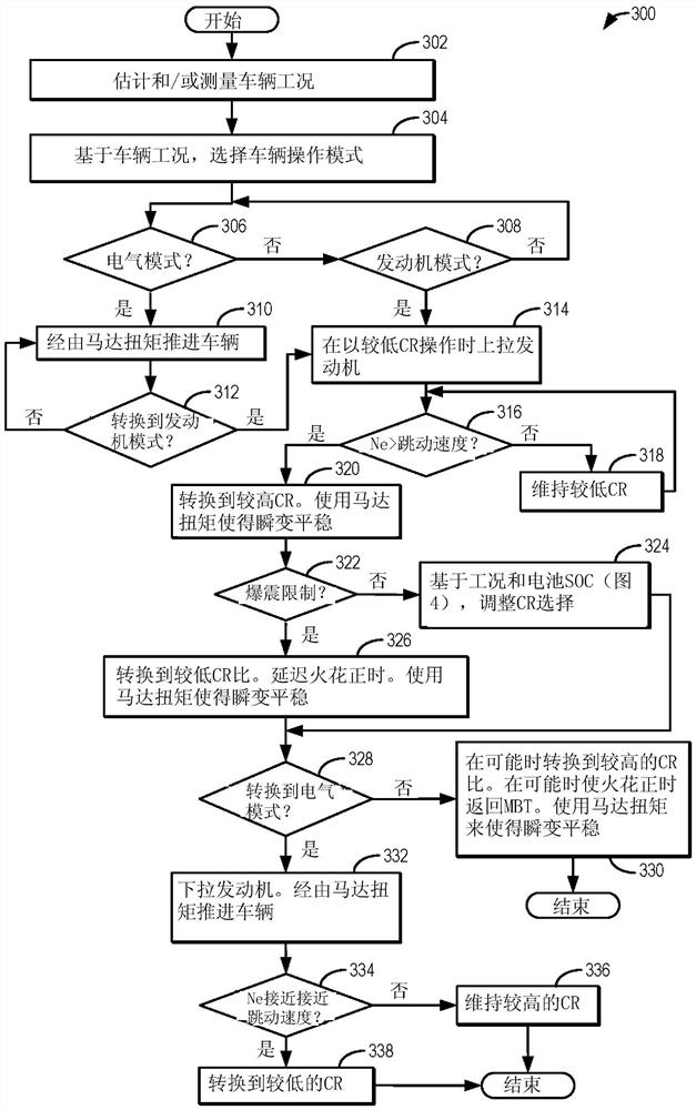
[0016] The following description relates to methods for improving hybrid vehicle systems such as figure 1 Systems and methods for fuel economy in a vehicle system. as reference figure 2 As described above, a vehicle system may include an engine configured with a variable compression ratio (VCR) mechanism capable of varying the compression ratio of the engine via mechanical adjustment. The controller can be configured to execute control routines such as image 3 example routine) to reduce the engine's compression ratio during engine pull-up and pull-down events, thereby reducing associated pumping losses and NVH. The controller can also execute routines (such as Figure 4 example routine) to choose between switching to an alternate compression ratio and maintaining the current compression ratio while using motor torque to meet demand deficits. refer to Figure 5-Figure 6 An example map is shown that may be used by a controller to select a compression ratio. Figure 7 Exa...


PUM


Abstract

The present invention relates to methods and systems for engine control. Methods and systems are provided for enhancing the benefits of variable compression ratio engines in hybrid vehicle systems. During engine pull-up and pull-down, the vehicle controller may maintain the engine at a lower compression ratio, especially when passing through low speed regions where compression bounce can occur. During engine operation, in response to changes in driver demand, the controller may choose to switch the compression ratio or maintain the current compression ratio while using motor torque to smooth undertorque, the selection being based on fuel economy.

Description

technical field [0001] The present description generally relates to methods and systems for controlling engine compression ratio in hybrid vehicle systems. Background technique [0002] The compression ratio of an internal combustion engine is defined as the ratio of the cylinder volume when the piston is at bottom dead center (BDC) to the cylinder volume when the piston is at top dead center (TDC). In general, the higher the compression ratio, the higher the thermal efficiency of the internal combustion engine. This in turn results in improved fuel economy and a higher ratio of output energy to input energy of the engine. In conventional engines, the compression ratio is fixed, and therefore engine efficiency cannot be optimized under operating conditions to improve fuel economy and engine power performance. [0003] Various techniques have been developed in order to enable the compression ratio of an engine to vary with engine operating conditions. An example method is ...

Claims


Application Information

Patent Timeline
Patent Type & Authority Patents(China)
IPC IPC(8): F02D15/04F02D43/00B60K6/24B60K6/40
CPCB60K6/24B60K6/40F02D15/04F02D35/027F02D37/02F02D13/0207F02D15/02F02D29/02F02D2200/101F02D2250/24F02D2200/60F02D2250/21Y10S903/905Y10S903/906Y10S903/91Y10S903/93B60W20/40B60W2540/10B60W2510/244B60K6/445Y02T10/62B60W20/17B60K6/26B60K6/365B60K6/48B60W10/06B60W10/08B60W2540/00B60W2710/0666B60W2710/083B60Y2200/92B60Y2300/43B60Y2306/09
Inventor K·J·米勒T·G·里昂D·R·马丁
Owner FORD GLOBAL TECH LLC
Why Eureka
Try Eureka