Floor-mopping cloth tensioning mechanism and floor mopping machine

A mopping machine and mopping cloth technology, applied in the direction of cleaning carpets, floors, machine parts, etc., can solve the problems of affecting the cleaning effect, inability to drive, and the machine is stuck, so as to improve the cleaning effect, improve the utilization efficiency, increase the The effect of a large contact area

Inactive Publication Date: 2017-11-17
GUANGDONG MIDEA KITCHEN APPLIANCES MFG CO LTD +1
View PDF5 Cites 13 Cited by
  • Summary
  • Abstract
  • Description
  • Claims
  • Application Information

AI Technical Summary

Problems solved by technology

They all need to raise the pollutant dust through the side brush or roller brush and then inhale it to achieve the purpose of cleaning. Therefore, this technology has its limitations that cannot be avoided in principle: 1. For extremely small pollutants or wet ground, due to pollution Objects cannot be lifted up well, so the cleaning effect is very poor; 2. The hair on the ground is often entangled on the side brush or roller brush, which affects the cleaning effect and even causes the machine to be stuck
However, this method requires the use of a mopping cloth with suitable elasticity and sufficient service life: if the elasticity is too large, that is, the mopping cloth is too soft, even if the mopping cloth is tensioned, there will be no gap between the driving wheel and the mopping cloth. Sufficient pressure; if the elasticity is too small, the dimensional design accuracy of the mopping cloth is relatively small, and even a small permanent plastic deformation on the mopping cloth during use will make it invalid and unable to drive

Method used


Image

  • Floor-mopping cloth tensioning mechanism and floor mopping machine
  • Floor-mopping cloth tensioning mechanism and floor mopping machine
  • Floor-mopping cloth tensioning mechanism and floor mopping machine

Examples


Embodiment Construction

[0040] In order to understand the above-mentioned purpose, features and advantages of the present invention more clearly, the present invention will be further described in detail below in conjunction with the accompanying drawings and specific embodiments. It should be noted that, in the case of no conflict, the embodiments of the present application and the features in the embodiments can be combined with each other.

[0041] In the following description, many specific details are set forth in order to fully understand the present invention. However, the present invention can also be implemented in other ways different from those described here. Therefore, the protection scope of the present invention is not limited by the specific details disclosed below. EXAMPLE LIMITATIONS.

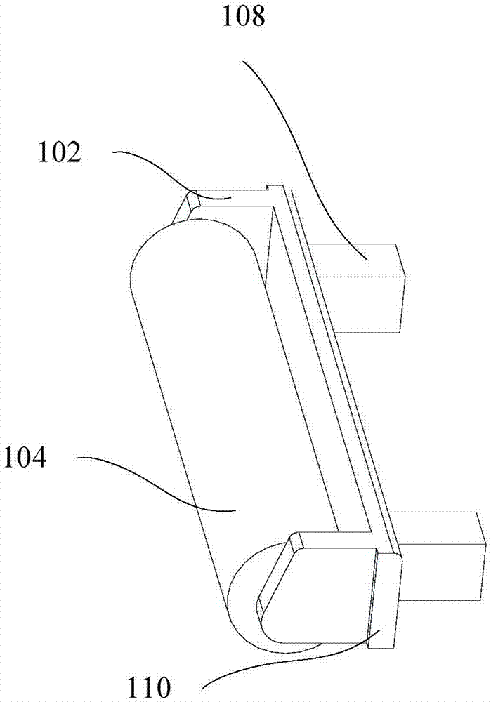
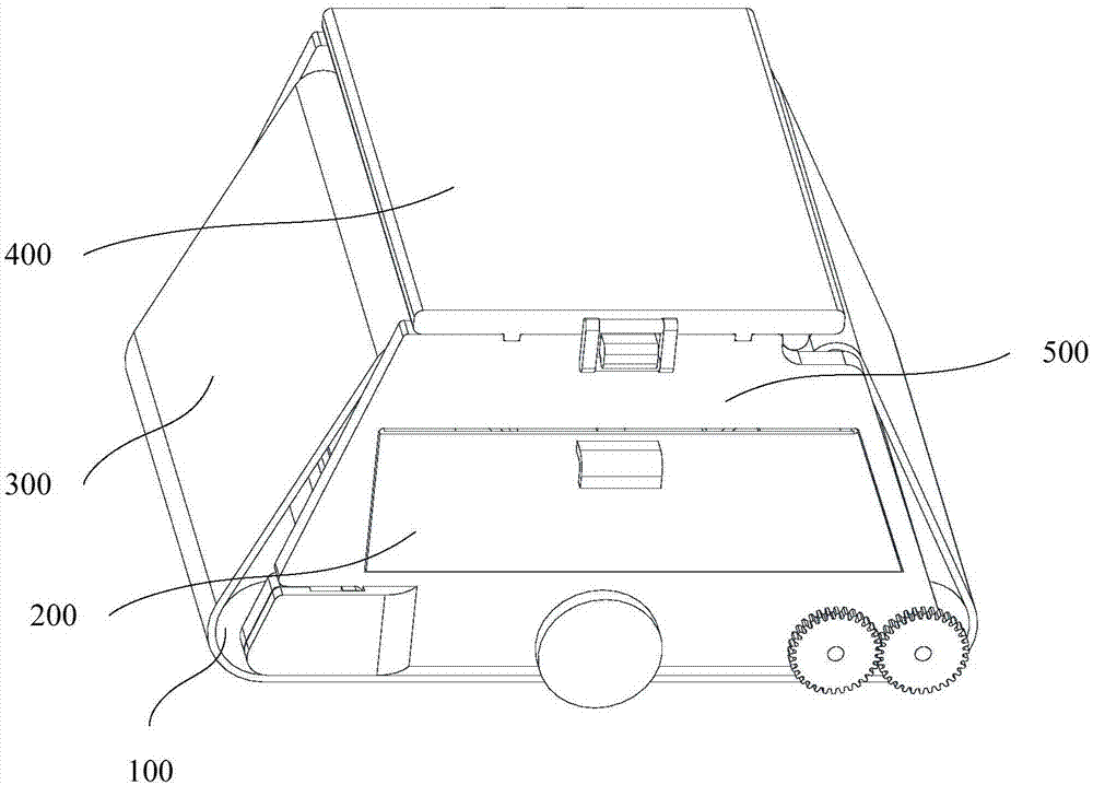
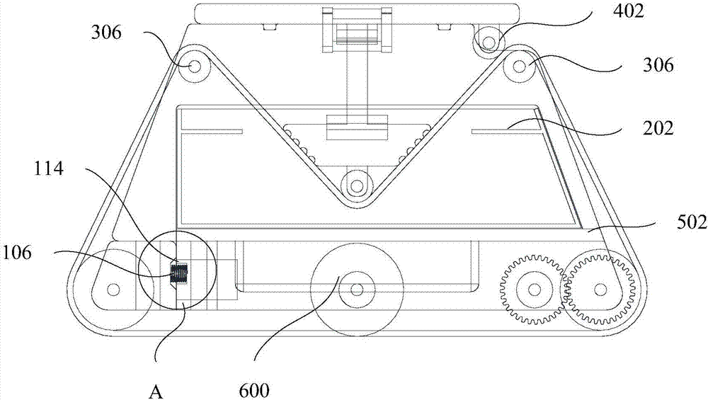
[0042] Refer below Figure 1 to Figure 5 The mopping cloth tensioning mechanism 100 and the mopping machine according to some embodiments of the present invention are described.

[0043] Such as f...


PUM


Abstract

The invention provides a floor-mopping cloth tensioning mechanism and a floor mopping machine. The floor-mopping cloth tensioning mechanism is applied to the floor mopping machine. The floor mopping machine includes floor mopping cloth and a machine body, the floor-mopping cloth tensioning mechanism is arranged on the machine body, and the floor-mopping cloth tensioning mechanism and the machine body are both sleeved with the floor mopping cloth; the floor-mopping cloth tensioning mechanism includes a fixing frame, a tensioning wheel and an elastic part, wherein the fixing frame is arranged on the machine body and can do reciprocating motion, the tensioning wheel is mounted on the fixing frame and can rotate around the fixing frame, and the elastic part is arranged on the machine body and faces one side of the fixing frame; under a working condition, the fixing frame compresses the elastic part, the floor mopping cloth is subjected to counter-acting force of the elastic part on the fixing frame and keeps tensioned. By the adoption of the floor-mopping cloth tensioning mechanism, the floor mopping cloth can have enough tensioning force, it is ensured that enough friction is generated between the floor mopping cloth and the floor, and the cleaning effect of the floor mopping machine is improved; meanwhile, even though slightly shaped or lengthened, the floor mopping cloth can be compensated through the floor-mopping cloth tensioning mechanism so that normal word cannot be influenced, and the user experience is improved.

Description

technical field [0001] The invention relates to the field of household appliances, in particular to a mopping cloth tensioning mechanism and a mopping machine. Background technique [0002] In order to solve the problem of carpet cleaning, vacuum cleaners were introduced in western countries, and based on these, vacuum cleaner robots were launched at the end of the 20th century. At present, the cleaning methods of sweeping robots are mainly divided into two-stage and three-stage. The two-stage type is to raise the dust through the side brush and then inhale it through the rear-end suction port to achieve the purpose of cleaning; the three-stage type is the cleaning structure of "side brush + roller brush + suction port". Compared with other two-stage types For products with a cleaning structure, the key point is to add a roller brush between the side brush and the suction port. The purpose is to sweep up the dust that is electrostatically adsorbed on the ground through the ...

Claims


Application Information

Patent Timeline
Patent Type & Authority Applications(China)
IPC IPC(8): A47L11/284A47L11/40
CPCA47L11/284A47L11/40A47L11/4047
Inventor 李永富李伟薛小山唐相伟
Owner GUANGDONG MIDEA KITCHEN APPLIANCES MFG CO LTD
Why Eureka
Try Eureka