Pipeline type sludge slag removal automation control system and control method

An automatic control and pipeline-type technology, applied in chemical instruments and methods, sludge treatment, separation methods, etc., can solve the problems of high cost of sludge treatment, low degree of automation, large slag particle radius, etc., and achieve the treatment effect Ideal, the effect of improving mixing efficiency and reducing operating costs

Active Publication Date: 2017-11-17
BEIJING DRAINAGE EQUIP
View PDF3 Cites 4 Cited by
  • Summary
  • Abstract
  • Description
  • Claims
  • Application Information

AI Technical Summary

Problems solved by technology

Some sewage treatment plants dry the sludge and then incinerate it or bury it deep, but the effect is not good, and the treatment cost is relatively high
In addition, the sludge also contains a large amount of slag. These slag particles have a large radius, and it is difficult to effectively separate them by conventional treatment, which also causes defects such as high sludge treatment costs. At the same time, this kind of sludge deslagging treatment The machine also has defects such as unreasonable structural design, poor processing effect, and low degree of automation.

Method used


Image

  • Pipeline type sludge slag removal automation control system and control method
  • Pipeline type sludge slag removal automation control system and control method
  • Pipeline type sludge slag removal automation control system and control method

Examples


Embodiment Construction

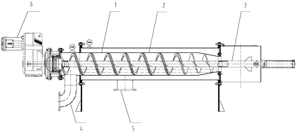
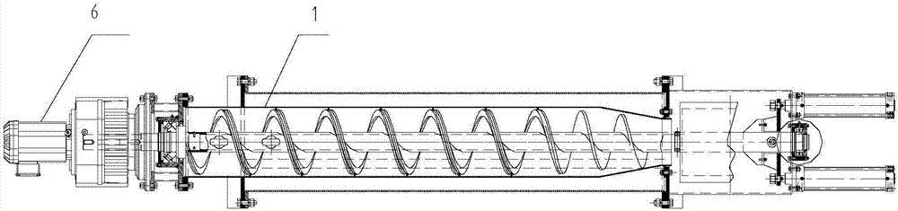
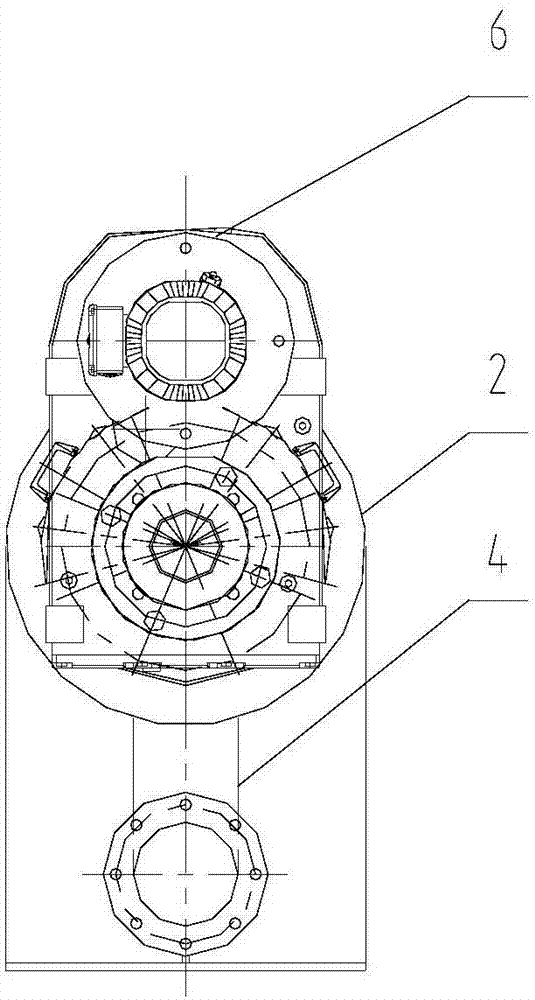
[0036] Attached below Figure 1-10 The pipeline type sludge removal automatic control system and its control method of the present invention are described in detail.

[0037] A pipeline-type sludge removal automation control system, characterized in that the automation control system includes a pipeline-type sludge removal machine 1 and a waterproof electric control box, wherein the pipeline-type sludge removal machine includes a horizontal horizontal The multifunctional filter cartridge 2 and the dewatering press device 3 arranged in the multifunctional filter cartridge are provided with a sludge inlet port 4 and a sludge outlet port 5 on the multifunctional filter cartridge; the cylinder of the multifunctional filter cartridge The inner cavity of the body is horizontally equipped with a spiral conveying assembly, which is electrically connected to the driving device 6; the spiral conveying assembly is respectively connected to the sludge inlet and the sludge outlet; the spir...


PUM


Abstract

The invention relates to a pipeline type sludge slag removal automation control system and a control method thereof. The system comprises a pipeline type sludge slag removal machine and a waterproof electric control box, wherein the pipeline type sludge slag removal machine comprises a multifunctional filter tube in horizontal transverse arrangement and a dewatering extrusion device arranged in the multifunctional filter tube; a sludge inlet and a sludge outlet are formed in the multifunctional filtering tube; a spiral type conveying assembly is transversely arranged in an inside cavity of a tube body of the multifunctional filter tube and is electrically connected with a driving device; the spiral type conveying assembly comprises a slag spiral conveying rod and a sludge filtering net; the slag is conveyed to the dewatering extrusion device through a spiral conveying rod; the dewatering extrusion device is connected with a slag outlet discharging device arranged at the outer side of the pipe body. The system and the method have the advantages that the structure is simple; the design is reasonable; the operation is reliable and stable; the automation degree is high; the stirring efficiency is high; the later-stage maintenance cost is low; the installation and the use are convenient and fast; the sludge can be effectively subjected to slag removal, recovery and reutilization, and the like.

Description

technical field [0001] The invention relates to the technical field of sewage treatment, in particular to a pipeline type sludge remover and its use method, which is mainly suitable for primary sludge, secondary sludge, mixed sludge, septic tank sewage in sewage treatment plants, etc. Removal of fine slag in mud. Background technique [0002] With the acceleration of urbanization and industrialization, the impact on the environment is becoming more and more serious. The protection of urban water environment is more important than before. The emergence of a large number of urban sewage treatment plants has effectively relieved the pressure on the urban water environment, but it has also brought The problem of how to deal with sludge in sewage treatment plants. Sludge is composed of bacterial micelles, organic matter, heavy metals, salts, and parasite eggs formed by various microorganisms. If it is not handled properly, it will easily cause secondary pollution, and it will in...

Claims


Application Information

Patent Timeline
Patent Type & Authority Applications(China)
IPC IPC(8): C02F11/00C02F11/18B01D29/11B01D29/60B01D29/64
CPCB01D29/11B01D29/117B01D29/60B01D29/64C02F11/00C02F11/18C02F2303/16C02F2303/24
Inventor 李喆秦春禹毕永伟郭勇张传光贺建国李艳高保华穆晓东王志锋
Owner BEIJING DRAINAGE EQUIP
Why Eureka
Try Eureka