Energy storage device capable of factory production for energy storage and power generation

An energy storage device and technology for energy storage and power generation, which are applied in wind power generation, sustainable manufacturing/processing, and wind engines for storing kinetic energy, etc., can solve the problems of low energy conversion rate and long energy storage time, and achieve wide adaptability, Effects of low cost and expanded scope of application

Pending Publication Date: 2017-11-17
姜庆有
View PDF10 Cites 0 Cited by
  • Summary
  • Abstract
  • Description
  • Claims
  • Application Information

AI Technical Summary

Problems solved by technology

[0013] The purpose of the present invention is to provide an energy storage device capable of industrialized energy storage and power generation, which solves the problems of long energy storage time and low energy conversion rate of existing energy storage power generation devices

Method used


Image

  • Energy storage device capable of factory production for energy storage and power generation
  • Energy storage device capable of factory production for energy storage and power generation
  • Energy storage device capable of factory production for energy storage and power generation

Examples


Embodiment 1

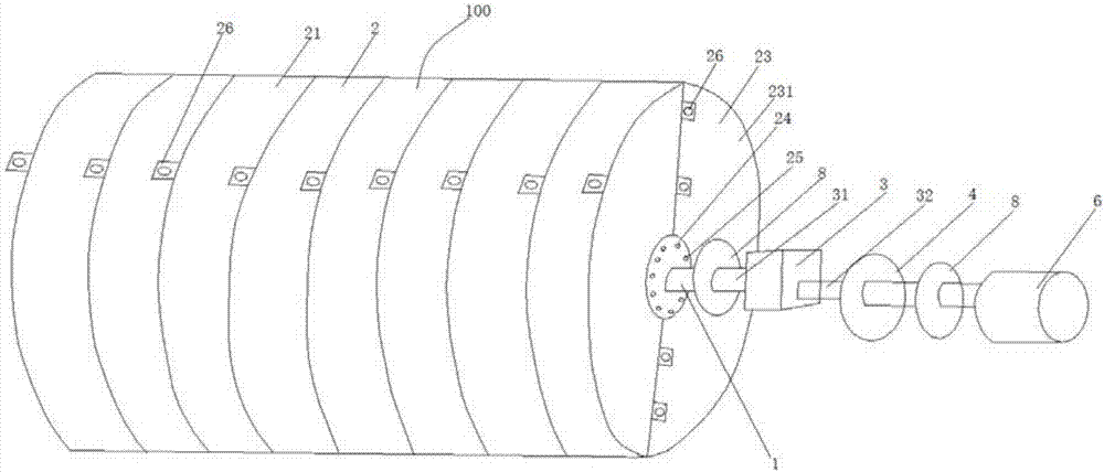
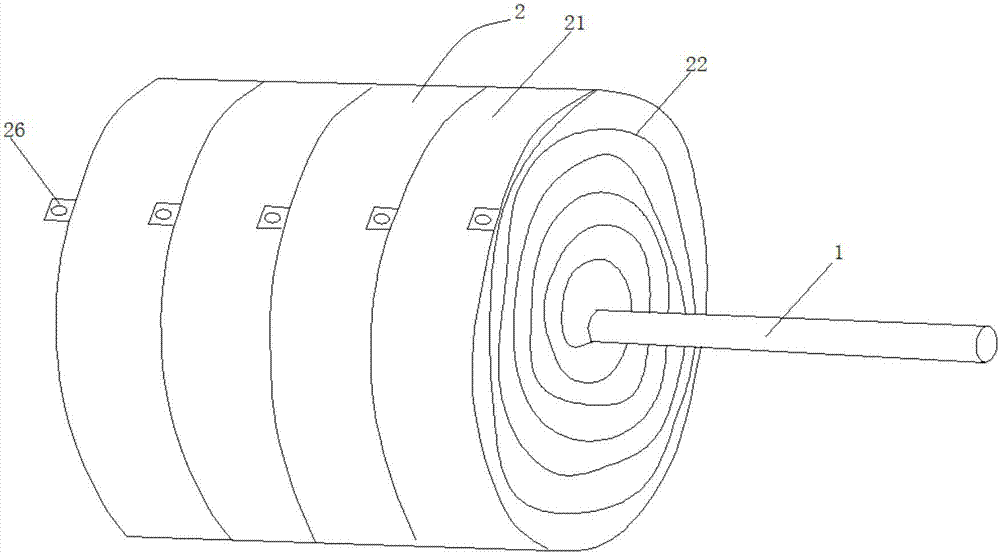
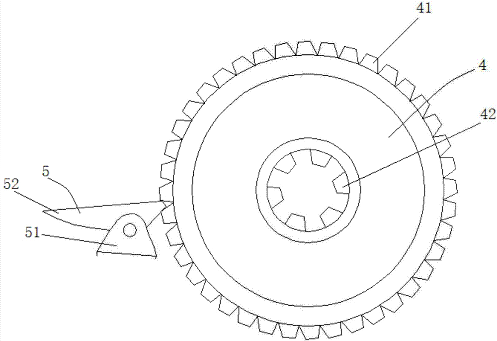
[0044] see Figure 1-5 , the present invention provides an energy storage device capable of industrialized energy storage and power generation. The energy storage device includes: a shaft 1; several energy storage units 2, each of which includes an annular casing 21 and an end The energy storage spring 22 connected in the annular casing 21, the energy storage unit 2 is sleeved on the shaft 1 through the other end of the energy storage spring 22 and forms a detachable connection with the shaft 1. The energy units 2 are sequentially arranged along the length direction of the shaft 1 to form a cylindrical energy storage body 100, one end of the shaft 1 protrudes to the outside of the energy storage body 100; a gear box 3, the output shaft 31 and the shaft The rod 1 extends out of the outer end of the energy storage main body 100 and is connected; a brake gear 4 is sleeved on the input shaft 32 of the gearbox 3; The support 51 and the detent 52 rotatably arranged on the support 51,...

Embodiment 2

[0061] A detachable connection is formed between the shaft 1 and the energy storage spring 22 via screws (not shown). All the other are with embodiment 1.

Embodiment 3

[0063] see Figure 4 , the surface of the input shaft 32 of the gearbox 3 located on both sides of the brake gear 4 is respectively provided with fixing grooves (not shown), and the two circular fixing parts 9 are sleeved on the input shaft 32 and clamped in the fixing grooves to form The fixing of the brake gear 4 on the input shaft 32 of the gear box 3, the two fixing parts 9 respectively include two symmetrically arranged semicircular fixing rings 91 matched with the input shaft 32 of the gear box 3, and the two ends of the fixing ring 91 Respectively extending outwards to form two fixing parts 92, fixing through holes 93 are provided on the fixing parts 92, the fixing parts 92 of the two fixing rings 91 are butted, the fixing parts 92 of the two fixing rings 91 are butting, the fixing through holes 93 on the adjacent two fixing parts 92 In communication, the two fixing rods 94 are respectively inserted into the two communicating fixing through holes 93 to form the fixing m...


PUM


Abstract

The invention discloses an energy storage device capable of factory production for energy storage and power generation. The energy storage device comprises a shaft lever, a plurality of energy storage units, a gear box, a braking gear, a brake member and a motor, wherein each energy storage unit comprises an annular cover shell and an energy storage spring respectively, and the shaft lever is sleeved with the energy storage units; the energy storage units form a cylindrical energy storage main body, and an output shaft of the gear box is connected with the outer side end of the shaft lever; an input shaft of the gear box is sleeved with the braking gear, and the brake member includes a support base and a block pin; the block pin can reach the position between each two adjacent external teeth of the braking gear, and braking of the braking gear is formed; the output end of the motor is connected with the end part of the input shaft of the gear box in a transmission mode; the motor drives the shaft lever to rotate through the gear box, and the energy storage springs contract under the action of the rotation of the shaft lever so as to achieve winding for energy storage. The energy storage device adopts the basic principle of the energy storage of an old type table clock, and the basic principle is enlarged infinitely within the permissible range of the capabilities of manufacture, transportation and installation, so that the purpose of the energy storage is achieved.

Description

technical field [0001] The invention belongs to the technical field of energy storage and power generation, and in particular relates to an energy storage device capable of industrialized energy storage and power generation. Background technique [0002] Problems existing in the prior art: [0003] 1. Pumped storage power generation [0004] 1. Limitations. The site selection for pumped storage power generation must have sufficient water sources and ravines close to the water sources, and then build dams for pumped storage power generation (generally using natural landform features, pumping power generation is not worth the loss). There is water without mountains No, even if there are mountains and no water, it determines its limitations and cannot be widely used; [0005] 2. Leakage and evaporation, if the energy storage power generation is not used for a long time, it will cause loss due to leakage and evaporation; [0006] 3. It takes a long time. Four pumped storage p...

Claims


Application Information

Patent Timeline
Patent Type & Authority Applications(China)
IPC IPC(8): F03G1/00F03G1/06F03D9/12
CPCF03D9/12F03G1/00F03G1/06Y02E10/72Y02E60/16Y02P90/50Y02P70/50Y02E70/30
Inventor 姜庆有
Owner 姜庆有
Why Eureka
Try Eureka