A vacuum belt dryer

A vacuum belt drying and chain technology, applied in progressive dryers, dryers, dry goods handling, etc., can solve the problems of heating plate length limitation, long stroke, short service life of conveyor belts, etc. Pull load, improve service life, and expand the effect of drying function

Active Publication Date: 2019-11-12
温兄控股集团股份有限公司
View PDF7 Cites 1 Cited by
  • Summary
  • Abstract
  • Description
  • Claims
  • Application Information

AI Technical Summary

Problems solved by technology

[0004] From the above mechanical analysis, it can be seen that the one-way friction drive mode in the prior art causes the high tensile load of the conveyor belt (and thus causes the short service life of the conveyor belt), and the length of the deviation-correcting shaft roller is long (the deviation-correcting shaft roller is generally higher than the conveyor belt The width and length of the belt is about 120mm), which leads to the complex and unreasonable frame structure of the dryer, the large tension of the cylinder and the long stroke, which leads to the limitation of the length of the heating plate
[0005] In addition, the vacuum drying equipment in the prior art usually adopts a hammer-based crushing device, and a screen is installed at the outlet of the powder material, and the crushed dry particles must be discharged through the screen. If the particles are too fine It is very easy to block the screen, resulting in the failure of smooth discharge

Method used


Image

  • A vacuum belt dryer
  • A vacuum belt dryer
  • A vacuum belt dryer

Examples


Embodiment Construction

[0027] The following examples are used to illustrate the present invention, but are not intended to limit the scope of the present invention.

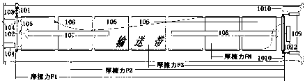
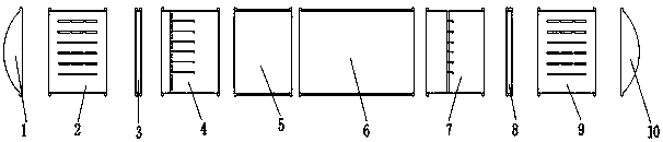
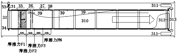
[0028] Such as Figure 2 to Figure 5 As shown, the vacuum belt dryer of the present invention includes a left hatch 1, a solid material feeding cabin 2, a left isolation airlock 3, a liquid extract feeding cabin 4, and an adjustment cabin connected in sequence from left to right 5. The main engine cabin 6, the powder material discharge cabin 7, the right isolation airlock 8, the solid material discharge cabin 9 and the right hatch door 10, also include a two-way chain drive device, and the two-way chain drive device includes a motor 31, drive shaft 32, sprocket wheel 34, conveyor belt connecting hole 35, conveyor belt staple 36, chain connecting plate 37, chain 38, multiple heating plates 39, conveyor belt 310, driven shaft 312 and cylinder 313, the described The output shaft of the motor 31 is connected with the drive shaft 32, and t...


PUM


Abstract

The invention discloses a vacuum belt drying machine. The vacuum belt drying machine comprises a left cabin door, a solid material feeding cabin, a left isolation air brake, a liquid extract feeding cabin, an adjusting cabin, a main engine cabin, a powder material discharging cabin, a right isolation air brake, a solid material discharging cabin and a right cabin door which are sequentially connected from left to right. A two-way chain-type drive unit comprises a motor, a driving shaft, sprocket wheels, conveyer belt connecting holes, conveyer belt staple bolts, chain connection plates, a chain, a plurality of heating plates, a conveyer belt, a driven shaft and cylinders. The motor drives the driving shaft to rotate; the sprocket wheels are arranged on the driving shaft; the sprocket wheels and the chain form an inlay transmission structure; the conveyer belt connecting holes are arranged in the conveyer belt, the chain connection plates are arranged between the chain and the conveyer belt, the conveyer belt staple bolts traverse the conveyer belt connecting holes and connect the chain, the chain connection plates and the conveyer belt together; the plurality of heating plates are arranged on the conveyer belt; and the driven shaft is connected with the cylinders, and the chain is connected between the driving shaft and the driven shaft.

Description

technical field [0001] The invention relates to the technical field of vacuum drying, in particular to a vacuum belt dryer. Background technique [0002] Vacuum drying equipment is widely used in the drying of snack food, fried food, fruit and vegetable chips, traditional Chinese medicine and other products. The host of vacuum drying equipment in the prior art usually adopts an integrated single body, and users cannot freely choose and match according to different shapes of materials and site conditions. [0003] In addition, the vacuum drying equipment in the prior art usually adopts a one-way friction drive method, which cannot effectively control the irregular lateral movement of the conveyor belt, and the conveyor belt is prone to deviation, so a special correction device (correction shaft ) to correct the conveyor belt. Such as figure 1 As shown, the deviation correction device of the vacuum belt dryer in the prior art includes a motor 101, a first deviation correcti...

Claims


Application Information

Patent Timeline
Patent Type & Authority Patents(China)
IPC IPC(8): F26B15/10F26B25/00B02C18/14B02C18/18
CPCB02C18/14B02C18/18F26B15/10F26B25/001
Inventor 姜沈阳项敬来陶耀镔姜瑞玉姜瑞岳
Owner 温兄控股集团股份有限公司
Why Eureka
Try Eureka