Multi-stage intensifying auxiliary sintering type ignition holding furnace and use method of same

An ignition holding furnace and auxiliary sintering technology, which is applied in the sintering field and can solve problems such as increased maintenance costs, finished sintered ore transfer strength, negative effects of reduction degree and low-temperature reduction pulverization rate, and low sintering quality

Pending Publication Date: 2017-11-17
ZHONGYE-CHANGTIAN INT ENG CO LTD
View PDF4 Cites 20 Cited by
  • Summary
  • Abstract
  • Description
  • Claims
  • Application Information

AI Technical Summary

Problems solved by technology

[0004] In the prior art, the heat preservation and ignition furnace of the sintering machine has the following defects: 1. The coke ratio is too high: since the air flow of the sintering machine passes through the material layer from top to bottom during production, before the combustion zone reaches the bottom of the sintering material layer, Bottom sintered material is in heat storage process
In actual production, due to the lack of feasible means and devices for segregation coke distribution, the coke distribution in the upper and lower material layers has to be in the same proportion, which not only wastes the amount of coke, but also increases unnecessary energy consumption, and the bottom The sintered material of the material layer will also deteriorate due to the high temperature
2. CO 2 Large emissions: Since the amount of coke added under the existing technology is much greater than the amount of coke required for actual and reasonable production, the CO produced by combustion during production 2 also increased significantly
3. The quality of sinter can not be effectively guaranteed: because the amount of coke added to the bottom of the sinter layer is far greater than the amount of coke required for actual and reasonable production, the temperature is too high during production, resulting in glass that is harmful to the quality of sinter Phase silicate, which has a negative impact on the share transfer strength, reduction degree and low-temperature reduction pulverization rate of the finished sinter
[0007] 1. The degree of freedom is not high: the device is fixed in height and length (along the running direction of the sintering machine), and the installation position of the device (distance from the end of the ignition furnace) cannot be changed. If the working conditions change, freedom cannot be realized. adjust;
[0008] 2. Poor adaptability: Due to the low degree of freedom, the injection device can only adapt to a single working condition, but cannot adapt to some sintering plants that frequently change materials or change machine speeds
[0009] 3. Short service life: Since the height of the injection device cannot be changed, and the height of the material surface changes in real time according to the change of working conditions, it is difficult to guarantee the distance between the lower edge of the device’s injection pipe and the upper edge of the material surface in actual production. Within a reasonable range, once the distance is too close, it is very easy to cause the blowing pipe to be burned by the high temperature material surface
[0010] 4. Low safety performance: Since the height of the injection device cannot be changed, and the height of the material surface changes in real time according to changes in working conditions, it is difficult to guarantee the distance between the lower edge of the device’s injection pipe and the upper edge of the material surface in actual production. Within a reasonable range, once the lower edge of the injection pipe of the device is too close to the material surface, it may cause gas fuel to burn in the injection pipe, thus causing a safety accident
[0011] 5. High maintenance cost: Since the height of the injection device cannot be changed, and the height of the material surface changes in real time according to the change of working conditions, it is difficult to ensure the distance between the lower edge of the device’s injection pipe and the upper edge of the material surface in actual production. Within a reasonable range, because the blowing pipe is easily burned by the high-temperature material surface, the manufacturer has to frequently replace the blowing pipe, which greatly increases the maintenance cost
[0012] 6. Unable to realize multi-process and multi-media coupling injection: the injection device in the prior art can only be used for single-medium injection gas, such as natural gas or coke oven gas, and the device cannot be installed with other needs such as hot air sintering when in use Coupling with the sintering auxiliary process at the same position
[0013] 7. The safety of the device is not high: the injection device in the prior art has no sealing means, so when the negative pressure of the large sintering flue is insufficient for some reason, the gas injected to the material surface does not have enough negative pressure If it is sucked into the material layer, it will overflow to the platforms on both sides of the sintering machine, causing personal injury to the operator
But this caused the sintering material with a thickness of 80mm above the combustion zone to be low in sintering quality and poor in effect because of too little coke distribution and no gas supplementary heat, and the overall yield decreased.

Method used


Image

  • Multi-stage intensifying auxiliary sintering type ignition holding furnace and use method of same
  • Multi-stage intensifying auxiliary sintering type ignition holding furnace and use method of same
  • Multi-stage intensifying auxiliary sintering type ignition holding furnace and use method of same

Examples


Embodiment approach

[0090] According to the first embodiment provided by the present invention, a multi-stage enhanced auxiliary sintering type ignition and holding furnace is provided:

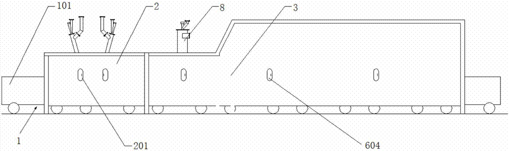
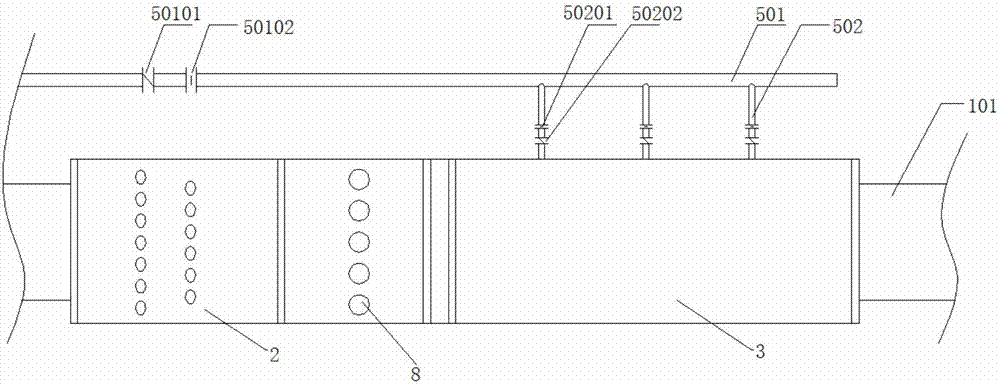
[0091] A multi-stage enhanced auxiliary sintering type ignition and holding furnace device includes a sintering machine 1, an ignition device 2 and an auxiliary combustion device 3. The sintering machine 1 includes a trolley 101 , and along the running direction of the trolley 101 , the ignition device 2 and the auxiliary combustion device 3 are sequentially arranged above the trolley 101 . The auxiliary combustion device 3 includes a hot air device 4 , an injection device 5 and an auxiliary combustion cover 6 . The hot air device 4 and the blowing device 5 are arranged on the auxiliary combustion cover 6 . The hot air device 4 includes a hot air duct 401 . The hot blast duct 401 stretches into or leads into the auxiliary combustion cover 6 . The blowing device 5 includes a gas main pipe 501 , a gas branch pi...

Embodiment 1

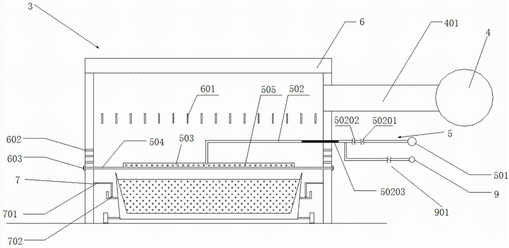
[0128] A multi-stage enhanced auxiliary sintering type ignition and holding furnace device includes a sintering machine 1, an ignition device 2 and an auxiliary combustion device 3. The sintering machine 1 includes a trolley 101 , and along the running direction of the trolley 101 , the ignition device 2 and the auxiliary combustion device 3 are sequentially arranged above the trolley 101 . The auxiliary combustion device 3 includes a hot air device 4 , an injection device 5 and an auxiliary combustion cover 6 . The hot air device 4 and the blowing device 5 are arranged on the auxiliary combustion cover 6 . The hot air device 4 includes a hot air duct 401 . The hot blast duct 401 stretches into or leads into the auxiliary combustion cover 6 . The blowing device 5 includes a gas main pipe 501 , a gas branch pipe 502 , a blowing pipe 503 and a bracket 504 . The gas main pipe 501 is arranged outside the auxiliary combustion cover 6 . One end of the gas branch pipe 502 is conn...

Embodiment 2

[0130] Embodiment 1 is repeated, except that the inner space of the auxiliary combustion cover 6 is also provided with a rectifying device 601 . The rectifying device 601 is located above the blowing pipe 503 of the blowing device 5 but below the air outlet of the hot blast duct 401 of the hot blast device 4 . The rectifying device 601 is a rectifying plate.


PUM


Abstract

A multi-stage intensifying auxiliary sintering type ignition holding furnace comprises a sintering machine (1), an ignition device (2) and an auxiliary combustion device (3), wherein the sintering machine (1) has a trolley (1); the ignition device (2) and the auxiliary combustion device (3) are orderly arranged on the trolley (1); the auxiliary combustion device (3) has a hot air device (4), a blow-injection device (5) and an auxiliary combustion cover (6); the hot air device (4) has a hot air pipeline (401); and the blow-injection device (5) has a fuel gas total pipe (501), a fuel gas branch pipe (502), a blow-injection pipe (503) and a rack (504). The multi-stage intensifying auxiliary sintering type ignition holding furnace can replace coke by partial fuel gas and hot smoke and achieves sintering bed segregation coke distribution effect via phase conversion; blow-injection device adjustability and freedom can be enhanced; multi-procedure multi-medium coupling blow-injection can be achieved; and the multi-stage intensifying auxiliary sintering type ignition holding furnace has great safety performance and high sintering quality.

Description

technical field [0001] The invention relates to an ignition and holding furnace and a use method thereof, in particular to a multi-stage enhanced auxiliary sintering type ignition and holding furnace and a use method thereof, belonging to the field of sintering. Background technique [0002] The sintering process is a key link in the ironmaking process. Its principle is to mix various powdery iron-containing raw materials with an appropriate amount of fuel and flux, add an appropriate amount of water, mix and pelletize the material on the sintering equipment to make the material A series of physical and chemical changes, sintered into blocks, which are sent to the blast furnace for the next step. [0003] In order to reduce the coke ratio and smelting cost of blast furnace ironmaking, blast furnaces often require high strength and high reducibility for sinter. In the sintering process, the sintered ore is generally required to have high strength, high yield, low return rate...

Claims


Application Information

Patent Timeline
Patent Type & Authority Applications(China)
IPC IPC(8): F27B21/00F27B21/08F27B21/14
CPCF27B21/00F27D19/00F27D99/0001F27D99/0073F27M2003/04F27D2019/004
Inventor 周浩宇朱飞
Owner ZHONGYE-CHANGTIAN INT ENG CO LTD
Why Eureka
Try Eureka