Conduit flow energy harvester

A technology of energy harvester and pipeline flow, which is applied in the direction of electrical components, piezoelectric effect/electrostrictive or magnetostrictive motors, generators/motors, etc., which can solve electromagnetic interference, cut-off, and unsuitable pipe diameters of power generation devices. Small occasions and other problems, to achieve the effects of strong fluid adaptability, improved reliability, and simple structure

Active Publication Date: 2017-11-17
ZHEJIANG NORMAL UNIVERSITY
View PDF2 Cites 3 Cited by
  • Summary
  • Abstract
  • Description
  • Claims
  • Application Information

AI Technical Summary

Problems solved by technology

Although some of the pipeline fluid leakage and anti-theft monitoring and alarm methods proposed are relatively mature at the technical level, the application of the anti-theft monitoring system for long-distance pipelines in my country is still in its infancy and has not yet been widely used. One of the main reasons is The power supply problem of the monitoring system has not been well solved: ①The cost of laying cables is high and it is easy to be cut off by criminals, which will affect the normal operation of the monitoring system; ②The battery power supply has a limited service time and needs to be replaced frequently. The remote transmission of monitoring information cannot be completed even when it is replaced in time
In recent years, in order to meet the self-power supply requirements of related wireless sensor monitoring systems, people have proposed various forms of turbine-type micro-fluid power generation devices. The biggest problem is that the structure is complex and the volume is relatively large, which is not suitable for pipelines with small diameters. In some occasions, some structures of power generation devices still have electromagnetic interference and other phenomena, and their popularization and application are restricted to a certain extent.

Method used


Image

  • Conduit flow energy harvester
  • Conduit flow energy harvester
  • Conduit flow energy harvester

Examples


Embodiment Construction

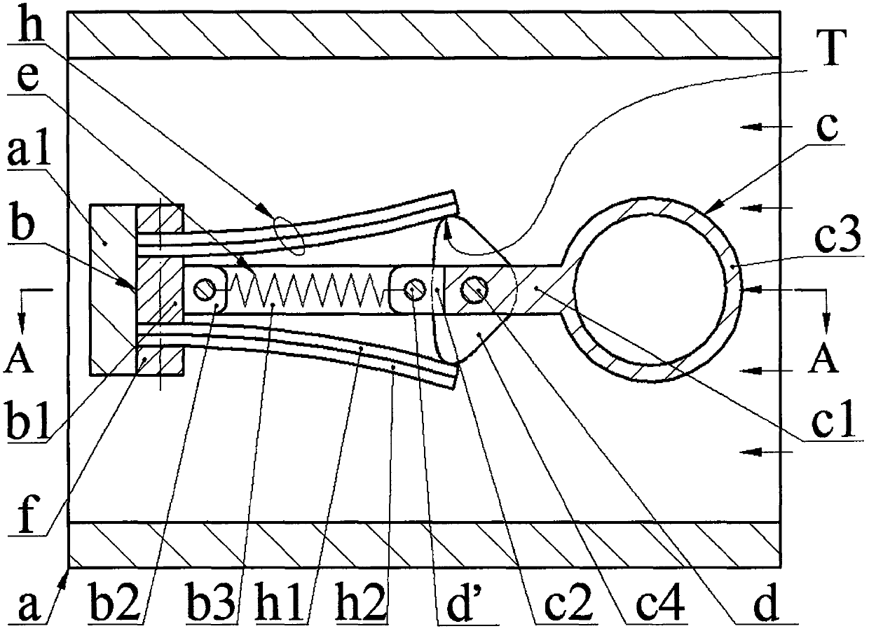
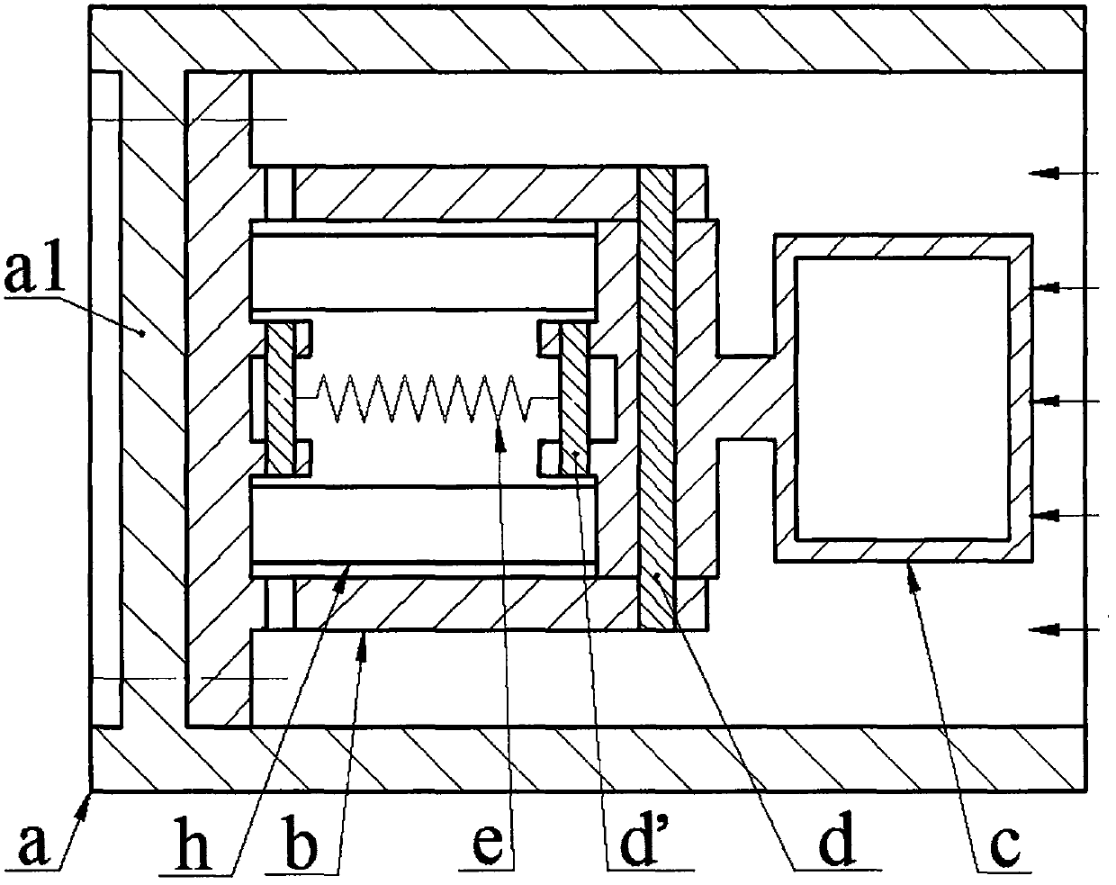
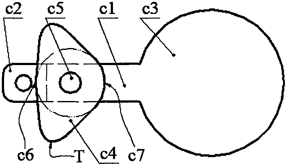
[0012] There is a crossbeam a1 inside the pipe a, a frame bottom b1, two inner ear plates b2 and two outer ear plates b3 on the frame b, the frame bottom b1 is installed on the cross beam a1 by screws; the left end of the rocker c1 of the exciter c is provided with Two rocker arm lugs c2, a hollow blunt body c3 on the right end, and cams c4 on the front and rear sides, the shaft hole c5 of the rocker arm c1 is set on the rotating shaft d, and the two ends of the rotating shaft d are respectively fixed on the two outer ear plates On b3; the pin shaft d' is installed on the inner ear plate b2 and the rocker arm ear plate c2, and the two ends of the spring e are respectively connected to the two pin shafts d'; the upper and lower sides of the frame bottom plate b1 are connected by screws and pressure plates A transducer h is installed. The transducer h is bonded by the substrate h1 and the piezoelectric film h2. The substrate h1 is installed close to the frame bottom plate b1. The...


PUM


Abstract

The present invention relates to a conduit flow energy harvester and belongs to the field of fluid power generation. A framework bottom plate, provided with inner and outer anchorage plates, is installed on the cross beam of a pipeline. The left end of a rocking arm of an exciter is provided with a rocking arm anchorage plate, and the right end of the rocking arm of the exciter is provided with a blunt body. The front and back sides of the exciter are provided with cams. The shaft hole of the rocking arm is sleeved on a rotating shaft. The rotating shaft is fixed onto the outer anchorage plate. The inner anchorage plate and the rocking arm anchorage plate are provided with pin shafts. The two ends of a spring are connected with the pin shafts. The upper and lower sides of the framework bottom plate are provided with energy transducers and the substrates of the energy transducers are arranged closer to the framework bottom plate. The free ends of the energy transducers are pressed against the cams. The contour curve of each cam is composed of two sections of arc profiles concentric with the shaft hole. In the contour curve of each cam, the distance between each arc profile and the center of the shaft hole is the shortest. Before the installation of energy transducers, the energy transducers are of a flat and straight structure. After the installation of energy transducers, the energy transducers are of a bent structure. Meanwhile, the free ends of the energy transducers and the vertex of the profile of each cam are in contact with each other. In the contour curve of each cam, the vertex of the profile is the largest in distance from the center of the shaft hole. The deformation amount of the energy transducers is the largest when the energy transducers are in contact with the vertex of the profile.

Description

technical field [0001] The invention belongs to the technical field of pipeline fluid power generation and pipeline monitoring, and in particular relates to a pipeline flow energy harvester. Background technique [0002] Due to corrosion, natural force majeure and human theft, long-distance pipelines for long-distance fluids such as oil and natural gas often leak during use. Frequent pipeline leakage not only causes huge economic losses, but also affects the surrounding natural environment. caused serious pollution. In the past, regular manual inspections were often used for maintenance. However, due to the long laying distance of oil and gas pipelines and the fact that they are often located in inaccessible or inaccessible places, it is difficult to detect leaks and maintain them in time by manual inspections. Therefore, various types of pipeline leakage monitoring and anti-theft systems have been proposed. Although some of the pipeline fluid leakage and anti-theft monito...

Claims


Application Information

Patent Timeline
Patent Type & Authority Applications(China)
IPC IPC(8): H02N2/18
CPCH02N2/185
Inventor 张忠华何恒钱陈松
Owner ZHEJIANG NORMAL UNIVERSITY
Why Eureka
Try Eureka