
Ironclad motor cast-aluminum rotor end surface burr cleaning device

A technology of cast aluminum rotor and cleaning device, which is applied in the direction of grinding drive device, manufacturing stator/rotor body, grinding/polishing safety device, etc. It can solve the problems of motor noise, inability to absorb burrs, and poor efficiency of manual grinding. Achieve the effect of improving the production qualification rate, avoiding the noise problem of the single motor, and improving the versatility

Inactive Publication Date: 2017-11-21
HEFEI TOTEM LONG MACHINERY DESIGN CO LTD
View PDF0 Cites 15 Cited by
  • Summary
  • Abstract
  • Description
  • Claims
  • Application Information

AI Technical Summary

Problems solved by technology

[0002] The cast aluminum rotor of the motor includes the rotor core and the aluminum ring cast on the end face. During the aluminum casting process, a mold is used to form the aluminum ring core cavity. The end face of the rotor core is against the end face of the core cavity of the mold, so that it will There are flaky flashes accumulated at the joint between the end face of the core cavity and the end face of the rotor core. These flashes will extend to the outside of the peripheral wall of the rotor core in the radial direction. In order to ensure the quality of the cast aluminum rotor, these flashes should be However, the existing motor manufacturers often use manual grinding when dealing with the burrs on the end face of the cast aluminum rotor. As a result, noise is generated during motor assembly

Method used


Image

  • Ironclad motor cast-aluminum rotor end surface burr cleaning device
  • Ironclad motor cast-aluminum rotor end surface burr cleaning device
  • Ironclad motor cast-aluminum rotor end surface burr cleaning device

Examples


Embodiment Construction

[0020] The technical solution of this patent will be further described in detail below in conjunction with specific embodiments.

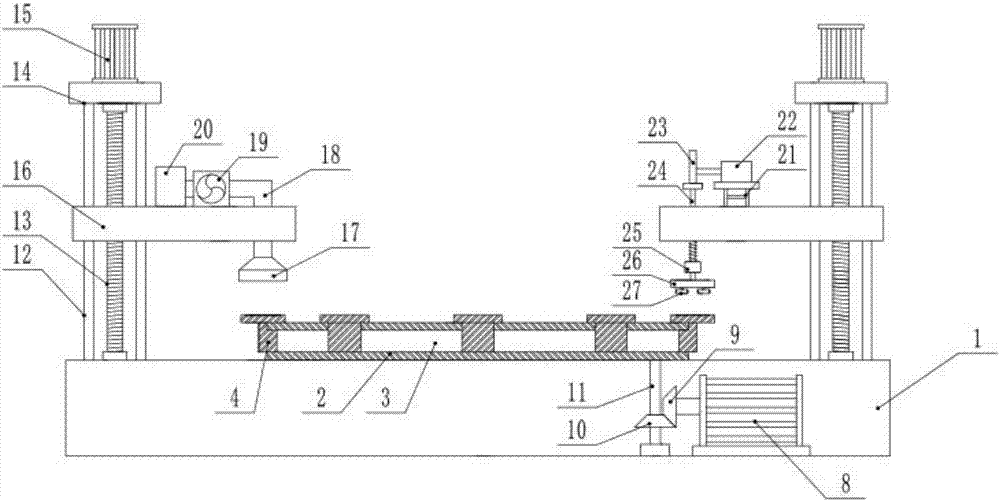
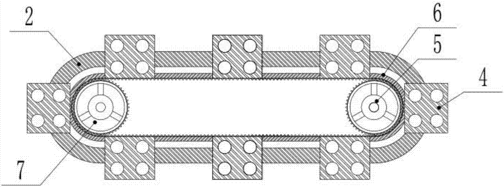
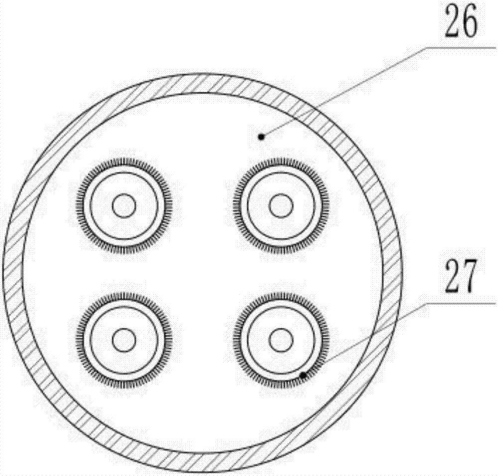
[0021] see Figure 1-3 , a device for cleaning burrs on the end surface of cast aluminum rotors of iron shell motors, including slideways 2, driving gears 5, toothed belts 6, driven gears 7, driving motors A8, screw rods 13, driving motors B15, lifting platforms 16, high-voltage suction The fan 19, the round wheel 26 and the grinding head 27, the upper surface of the base 1 is fixed with a slideway 2 by screws, the outer surface of the slideway 2 is provided with a chute 3, and several groups of slideways are installed on the chute 3. Block 4, the upper surface of the slider 4 has a rotor placement groove, the rotor placement groove is a circular groove, and the depth of the circular groove is 30-35mm, the inside of the base 1 is a hollow structure, and the inside of the base 1 is fixedly installed with a drive The motor A8 and the output shaft of...


PUM


Abstract

The invention discloses an ironclad motor cast-aluminum rotor end surface burr cleaning device, which comprises a slideway, a driving gear, a toothed belt, a driven gear, a driving motor A, a screw rod, a driving motor B, a lifting table, a high-pressure suction fan, a circular wheel and grinding heads, wherein a plurality of groups of sliding blocks are arranged on a sliding groove in a sliding mode; a rotor placement groove is opened in the upper surface of each sliding block; the output shaft of the driving motor B is connected with the screw rod through a coupler; the lifting table is arranged on the screw rod in a threaded mode; the lower side of the lifting table is provided with a fan cover; the upper side of the lifting table is provided with the high-pressure suction fan; the output shaft of a rotation motor is provided with the circular wheel in a rotating mode; and the lower side of the circular wheel is fixedly provided with a plurality of groups of grinding heads. While the device grinds rotor end surface burrs, the ground burrs can also be absorbed, burr scrap can be prevented from being attached to the surface of the rotor as much as possibly, the problem of single motor noise caused by various friction noise in the case of final assembly can be effectively avoided, and the production qualification rate of the motor can be improved.

Description

technical field [0001] The invention relates to a burr cleaning device, in particular to a burr cleaning device on the end face of a cast aluminum rotor of an iron shell motor. Background technique [0002] The cast aluminum rotor of the motor includes the rotor core and the aluminum ring cast on the end face. During the aluminum casting process, a mold is used to form the aluminum ring core cavity. The end face of the rotor core is against the end face of the core cavity of the mold, so that it will There are flaky flashes accumulated at the joint between the end face of the core cavity and the end face of the rotor core. These flashes will extend to the outside of the peripheral wall of the rotor core in the radial direction. In order to ensure the quality of the cast aluminum rotor, these flashes should be However, the existing motor manufacturers often use manual grinding when dealing with the burrs on the end face of the cast aluminum rotor. As a result, noise is gener...

Claims


Application Information

Patent Timeline
Patent Type & Authority Applications(China)
IPC IPC(8): H02K15/02B24B9/04B24B41/00B24B47/12B24B55/06
CPCH02K15/02B24B9/04B24B41/005B24B47/12B24B55/06
Inventor 杨辉
Owner HEFEI TOTEM LONG MACHINERY DESIGN CO LTD
Learn More