Multi-electrode ablation device
A multi-pole and detection device technology, applied in medical science, heating surgical instruments, ultrasonic therapy, etc., can solve the problems of low efficiency, inability to detect the adhesion of electrodes and tracheal wall, long operation time, etc.
- Summary
- Abstract
- Description
- Claims
- Application Information
AI Technical Summary
Problems solved by technology
Method used
Image
Examples
Embodiment 1
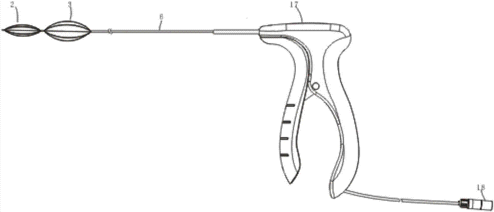
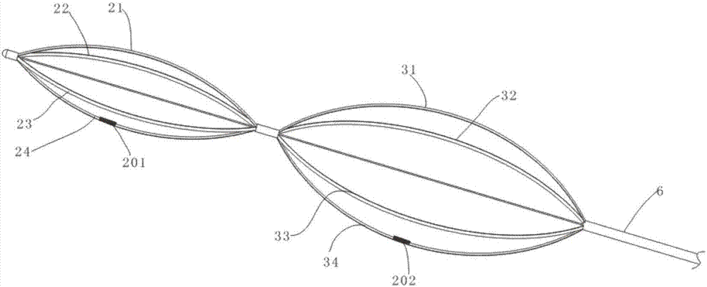
[0035] The present invention relates to a device for delivering energy functions in the trachea and bronchi, and further relates to a multipolar ablation device, such as figure 1 As shown, the device mainly includes a first electrode assembly 2 , a second electrode assembly 3 , a guide tube 6 , a handle 17 , and a connector 18 . Such as figure 2 As shown, the first electrode assembly 2 and the second electrode assembly 3 are arranged continuously in the axial direction of the guide tube body 6, and the head end of the electrode assembly is provided with an anti-damage structure 1, which is used to fix the first electrode assembly 2 and the first electrode assembly. The electrode assembly 2 and the second electrode assembly 3 are connected by a support member 4, the proximal end of the first electrode assembly 2 and the distal end of the second electrode assembly 3 are fixed on the support member 4, and the distal end of the pulling wire 5 is connected to the head end The ant...
Embodiment 2
[0038] Such as Figures 6 to 8 It is the second embodiment of the device. A first balloon 11 and a second balloon 12 are arranged under the first electrode assembly 2 and the second electrode assembly 3, and a first balloon airway 15 is arranged at the proximal end of the first balloon 11. The proximal end of the second balloon 12 is provided with a balloon second airway 16 . The first balloon 11 and the second balloon 12 are isolated from each other, and the first airway 15 and the second airway 16 are independent of each other to provide gas for the first balloon 11 and the second balloon 12. When the gas passes through the balloon When the tract enters the balloon, the first electrode 71, the second electrode 72, the third electrode 73, the fourth electrode 74, the fifth electrode 81, the sixth electrode 82, the seventh electrode 83, and the eighth electrode 84 expand under pressure. , the electrode assembly expands, and the gas intake volume is controlled by an external i...
Embodiment 3
[0041] Such as Figure 9Shown is the third embodiment, the first ring electrode 13 and the second ring electrode 14 are spirally arranged on the first balloon 11 and the second balloon 12, when the balloon is inflated, the first ring electrode 13 and the second The outer diameter of the ring electrode 14 becomes larger. The first ring electrode 13 and the second ring electrode 14 are provided with independent electrode wires. When in use, each electrode passes through the trachea tissue and the control circuit board to form a loop, and each electrode can independently detect the adhering resistance between the electrode and the tissue. . The ring electrode 13 and the ring electrode 14 are respectively provided with a temperature sensor 201 and 202, which can independently detect the temperature of the tissue around the electrode assembly.
[0042] Such as Figure 10 As shown, the handle 17 is provided with an indicator light 19. Theoretically, radiofrequency ablation can be...
PUM
| Property | Measurement | Unit |
|---|---|---|
| Resistance | aaaaa | aaaaa |
| Shore hardness | aaaaa | aaaaa |
Abstract
Description
Claims
Application Information
 - R&D
- Intellectual Property
- Life Sciences
- Materials
- Tech Scout
- Unparalleled Data Quality
- Higher Quality Content
- 60% Fewer Hallucinations
Browse by: Latest US Patents, China's latest patents, Technical Efficacy Thesaurus, Application Domain, Technology Topic, Popular Technical Reports.
© 2025 PatSnap. All rights reserved.Legal|Privacy policy|Modern Slavery Act Transparency Statement|Sitemap|About US| Contact US: help@patsnap.com


