Special anesthesia machine for anesthesiology departments

A technology of anesthesia machine and anesthesiology department, which is applied in the field of anesthesia machines, can solve the problems of discomfort, negative pressure of breathing air bag, and low efficiency of drug delivery, and achieve the effect of scientific and reasonable structure, safe and convenient use

Inactive Publication Date: 2017-11-24
张乙莲
View PDF5 Cites 7 Cited by
  • Summary
  • Abstract
  • Description
  • Claims
  • Application Information

AI Technical Summary

Problems solved by technology

[0004] The purpose of the present invention is to provide a special anesthesia machine for the department of anesthesiology, in order to solve the problem that the original anesthesia machine proposed in the above-mentioned background technology cannot absorb all the anesthetic drugs, and the drugs that cannot be absorbed are in the process of exhalation. The exhaust gas is exhausted from the anesthesia mask into the anesthesia machine, and the built-in residual gas removal system will not be able to clean the exhaust gas. Leakage of the exhaust gas in the air will bring a series of uncomfortable feelings such as numbness and headache to the doctor, which will affect the doctor's treatment of the patient. For anesthesia treatment, completely collecting the exhaust gas in the exhaust gas tank may affect the negative pressure of the breathing air bag, resulting in low delivery efficiency of drugs to the patient and insufficient anesthesia for the patient

Method used


Image

  • Special anesthesia machine for anesthesiology departments
  • Special anesthesia machine for anesthesiology departments
  • Special anesthesia machine for anesthesiology departments

Examples


Embodiment Construction

[0019] The following will clearly and completely describe the technical solutions in the embodiments of the present invention with reference to the accompanying drawings in the embodiments of the present invention. Obviously, the described embodiments are only some, not all, embodiments of the present invention. Based on the embodiments of the present invention, all other embodiments obtained by persons of ordinary skill in the art without making creative efforts belong to the protection scope of the present invention.

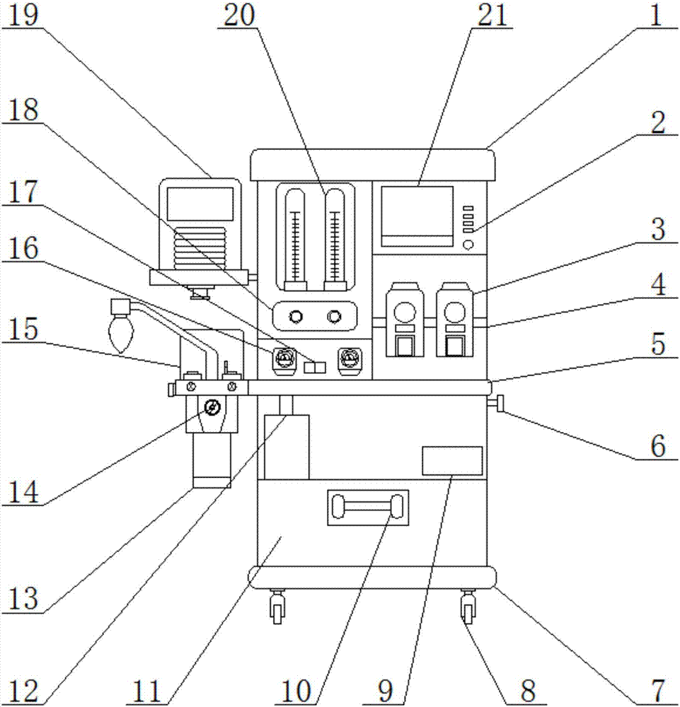
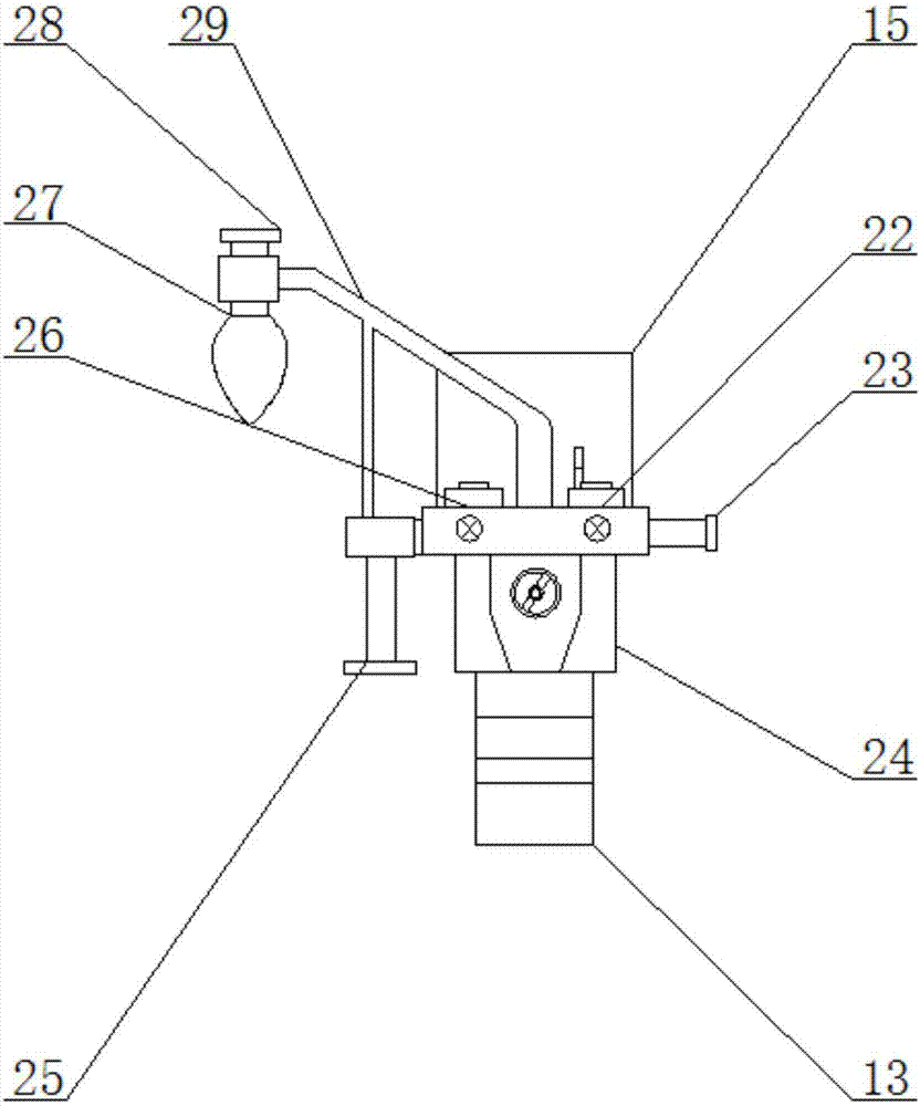
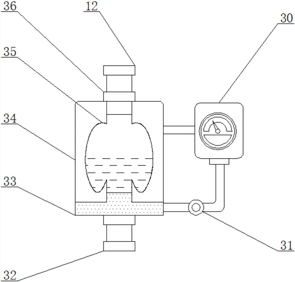
[0020] see figure 1 , figure 2 and image 3 , the present invention provides a technical solution: comprising an anesthesia body 1, a bellows 19, a carbon dioxide concentration sensor 24 and a waste gas treatment tank 34, a flow meter 20 is arranged above the front surface of the anesthesia body 1, and a display panel is arranged on the right side of the flow meter 20 21. An index setting button 2 is set on the right side of the display panel 21, and a medi...


PUM


Abstract

The invention discloses a special anesthesia machine for anesthesiology departments. The special anesthesia machine comprises an anesthesia machine body, an air box, a carbon dioxide concentration sensor and a waste gas treatment tank. Flow meters are arranged on the upper side of the front surface of the anesthesia machine body, a display panel is arranged on the right side of the corresponding flow meter, and index setting buttons are arranged on the right side of the display panel. The special anesthesia machine has the advantages that the special anesthesia machine is additionally provided with the waste gas treatment tank on the basis of the original waste gas treatment system, a filter is arranged in the waste gas treatment tank and is filled with filter liquid, an activated carbon layer is arranged below the filter, most of waste gas can be collected in a pressure tank after the waste gas flows through the waste gas treatment tank and is filtered by double layers, only a small portion of waste gas can be exhausted into an operating room, and the little filtered waste gas is free of harm on doctors; expiration and inspiration of patients can be simulated by the filter, cleaned gas keeps constant with breathing gas of the patients, integral negative pressures of the special anesthesia machine hardly can be changed, anesthetics and oxygen can keep being normally delivered to the respiratory tracts of the patients, and accordingly the stability of anesthesia operation can be guaranteed.

Description

technical field [0001] The invention belongs to the technical field of medical equipment, and in particular relates to an anesthesia machine dedicated to the anesthesiology department. Background technique [0002] Since Ronning first applied ether anesthesia in 1846, inhalation anesthesia has been perfected day by day. The development of modern pharmacology, the advancement of science and technology, especially the application of computer technology, have greatly improved the level of modern inhalation anesthesia. Inhalational anesthesia is easy to control, safe and effective. It is the first choice when performing surgery in the current hospital. The so-called anesthesia refers to the method of temporarily losing all or part of the organism's consciousness in order to perform surgical treatment. There are many methods of anesthesia, such as acupuncture anesthesia, injection anesthesia and inhalation anesthesia. The current method of general anesthesia in hospitals is s...

Claims


Application Information

Patent Timeline
Patent Type & Authority Applications(China)
IPC IPC(8): A61M16/01B01D53/18B01D53/04
CPCA61M16/0003A61M16/01A61M2016/0033A61M2202/0241A61M2205/75B01D53/04B01D53/18B01D2253/102B01D2257/402A61M2202/0007Y02C20/10
Inventor 张乙莲
Owner 张乙莲
Why Eureka
Try Eureka