
Gas distribution and methanation system as well as methanation process system

A process system and methanation technology, applied in the direction of gas fuel, organic chemistry, petroleum industry, etc., can solve the problems of increasing equipment investment, reducing metal wall temperature, and large reaction temperature rise, so as to reduce the difficulty of structural design and reduce the material Requirements, the effect of reducing equipment investment

Pending Publication Date: 2017-11-24
BEIJING HUAFU ENG
View PDF0 Cites 0 Cited by
  • Summary
  • Abstract
  • Description
  • Claims
  • Application Information

AI Technical Summary

Problems solved by technology

In the gas-partitioning methanation stage, due to the H in the syngas 2 And CO content is high, the reaction temperature rise is large, the outlet temperature of the reactor is generally controlled at 600 ~ 700 ℃, usually the outlet gas of the reactor directly enters the waste heat boiler for heat recovery, because the inlet temperature of the waste heat boiler is very high, the inlet tube box of the waste heat boiler needs to be Design thicker refractory lining and thermal insulation lining to reduce the metal wall temperature, which not only increases the equipment investment, but also increases the possible safety risks caused by damage to the refractory lining and thermal insulation lining. At the same time, due to the high inlet temperature of the waste heat boiler, The requirements for the material of the heat exchange tube protection sleeve of the waste heat boiler increase, and the structural design difficulty of the flexible thin tube sheet of the waste heat boiler will increase accordingly

Method used


Image

  • Gas distribution and methanation system as well as methanation process system
  • Gas distribution and methanation system as well as methanation process system
  • Gas distribution and methanation system as well as methanation process system

Examples


Embodiment 1

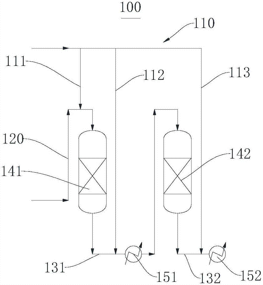
[0034] Please refer to figure 1 This embodiment provides a gas distribution methanation system 100 , including a first gas distribution pipe 110 , a second gas distribution pipe 120 , a first gas transmission pipe 131 , a first reactor 141 and a first waste heat recovery device 151 . The first gas distribution pipe 110 is respectively connected to the first reactor 141 and the first gas delivery pipe 131, the second gas distribution pipe 120 is connected to the first reactor 141, and the first reactor 141 is connected to the first waste heat recovery device through the first gas delivery pipe 131. 151 connections.

[0035] Specifically, the first gas distribution pipe 110 and the second gas distribution pipe 120 are used to input gas into the first reactor 141 and the first waste heat recovery device 151 . A catalyst is placed in the first reactor 141 to catalyze the reaction. A large amount of CO-rich gas can cause catalyst poisoning, but a large amount of H-rich 2 This do...

Embodiment 2

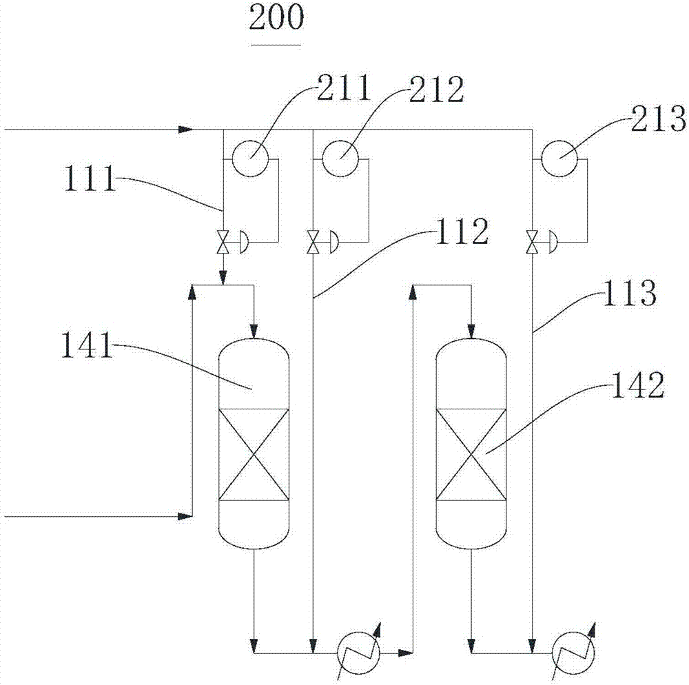
[0041] Please refer to figure 2 , this embodiment provides a gas distribution methanation system 200 .

[0042] The difference between the gas distribution methanation system 200 and the gas distribution methanation system 100 mainly lies in:

[0043] The gas distribution methanation system 200 includes a first flow regulator 211, a second flow regulator 212, and a third flow regulator 213. The first flow regulator 211 is arranged on the first pipeline 111, and is used to adjust the flow rate of the first pipeline 111. The flow rate of the CO-enriched gas, the second flow regulator 212 is arranged in the second pipeline 112 for adjusting the flow rate of the CO-enriched gas transported by the second pipeline 112, and the third flow regulator 213 is arranged in the third pipeline 113 for adjusting The flow rate of the CO-enriched gas delivered by the third pipeline 113. The first flow regulator 211, the second flow regulator 212, and the third flow regulator 213 adjust the C...

Embodiment 3

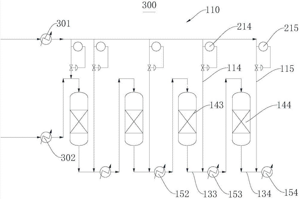
[0047] Please refer to image 3 , this embodiment provides a gas distribution methanation system 300 .

[0048] The difference between gas distribution methanation system 300 and gas distribution methanation system 200 mainly lies in:

[0049] Gas distribution methanation system 300 includes 4 stages of reactions. Specifically, it includes the third reactor 143, the third gas transmission pipe 133, the third waste heat recovery device 153, the fourth reactor 144, the fourth gas transmission pipe 134, and the fourth waste heat recovery device connected in sequence to the second waste heat recovery device 152. 154. The first gas distribution pipe 110 includes a fourth pipeline 114 for delivering CO-rich gas to the third gas delivery pipe 133 and a fifth pipeline 115 for delivering CO-rich gas to the fourth gas delivery pipeline 134. The fourth pipeline 114 and the fifth pipeline 115 are respectively A fourth flow regulator 214 and a fifth flow regulator 215 are provided.

[...


PUM


Abstract

The invention provides a gas distribution methanation system and a methanation process system, which relate to the technical field of chemical industry. A gas distribution methanation system, comprising a first gas distribution pipe, a second gas distribution pipe, a first gas transmission pipe, a first reactor and a first waste heat recovery device, the first gas distribution pipe is connected to the first reactor and the first gas transmission pipe respectively The second gas distribution pipe is connected to the first reactor, and the first reactor is connected to the first waste heat recovery device through the first gas transmission pipe. The structure is simple, the equipment investment is low, the design difficulty is low, and the safety is high. A methanation process system includes the above gas distribution methanation system. The structure is simple, the device investment is low, the system is energy-saving, and the product is stable.

Description

technical field [0001] The invention relates to the technical field of chemical industry, in particular to a gas distribution methanation system and a methanation process system. Background technique [0002] The methanation process refers to the CO, CO 2 and H 2 Under the action of certain temperature, pressure and catalyst, the process of methanation reaction to generate methane occurs. This reaction is a strongly exothermic reaction (a strong exothermic reaction usually refers to a reaction with an enthalpy value greater than 200kJ / mol). Under the usual composition of synthesis gas, each percentage point of CO methanation can produce an adiabatic temperature rise of 74°C. per percent CO 2 Methanation can produce an adiabatic temperature rise of 60°C. Limited by thermodynamic equilibrium, multi-stage series reactors are usually required to achieve complete methanation of syngas. Using conventional gasified coal gas as raw material, after conversion and purification, i...

Claims


Application Information

Patent Timeline
Patent Type & Authority Applications(China)
IPC IPC(8): B01J8/00B01J8/02C07C1/04C07C9/04C10L3/08
CPCB01J8/02B01J8/00B01J8/001B01J8/0278C07C1/0405C10L3/08
Inventor 王志远陈兆文兰玉顺任楠楠陈书成张立宁
Owner BEIJING HUAFU ENG
Learn More