
Numerical-control machine tool cleaning device

A technology for CNC machine tools and cleaning devices, applied in metal processing machinery parts, maintenance and safety accessories, metal processing equipment, etc., can solve problems affecting production sales rate, debris residue, CNC machine tool damage, etc. Convenience and damage avoidance effect

Inactive Publication Date: 2017-11-24
苏州圣凡自动化科技有限公司
View PDF0 Cites 12 Cited by
  • Summary
  • Abstract
  • Description
  • Claims
  • Application Information

AI Technical Summary

Problems solved by technology

[0006] 1. Generally, when the CNC machine tool is in use, since the processed parts are metal parts, debris and some metal dust will inevitably be generated during the processing process. If these debris and metal dust cannot be cleaned in time, it will damage the CNC machine tool. It will cause a certain impact, and in severe cases, it will cause damage to the CNC machine tool. However, due to the number of factory personnel and management reasons, there is generally no special person to clean up the debris inside the CNC machine tool. Therefore, manual cleaning is not sufficient, and it is easy to cause debris residues
[0007] 2. Under normal circumstances, the debris cleaning of CNC machine tools is mostly done when the power is off, and the staff uses clean water to flush the interior of the processing room. Since there are a large number of electrical equipment inside the CNC machine tool, it is necessary to wait for the CNC machine tool to clean up after the cleaning is completed. The equipment can be used again after the inside of the machine tool is completely dry, which will not only affect the production and sales rate, but if the inside of the equipment is not completely dry before being powered on, it will cause damage to the equipment

Method used


Image

  • Numerical-control machine tool cleaning device
  • Numerical-control machine tool cleaning device
  • Numerical-control machine tool cleaning device

Examples


Embodiment Construction

[0030] The following will clearly and completely describe the technical solutions in the embodiments of the present invention with reference to the accompanying drawings in the embodiments of the present invention. Obviously, the described embodiments are only some, not all, embodiments of the present invention. Based on the embodiments of the present invention, all other embodiments obtained by persons of ordinary skill in the art without making creative efforts belong to the protection scope of the present invention.

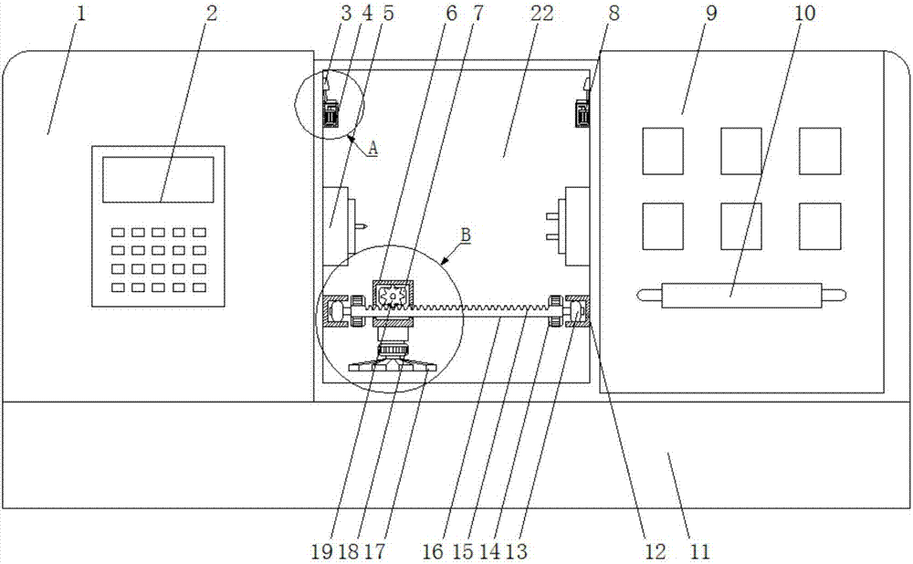
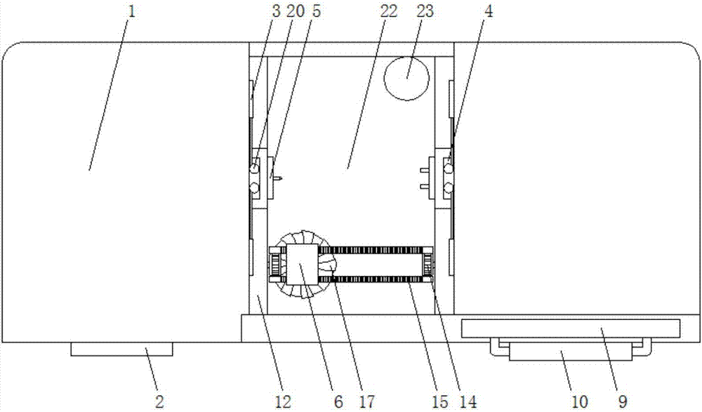
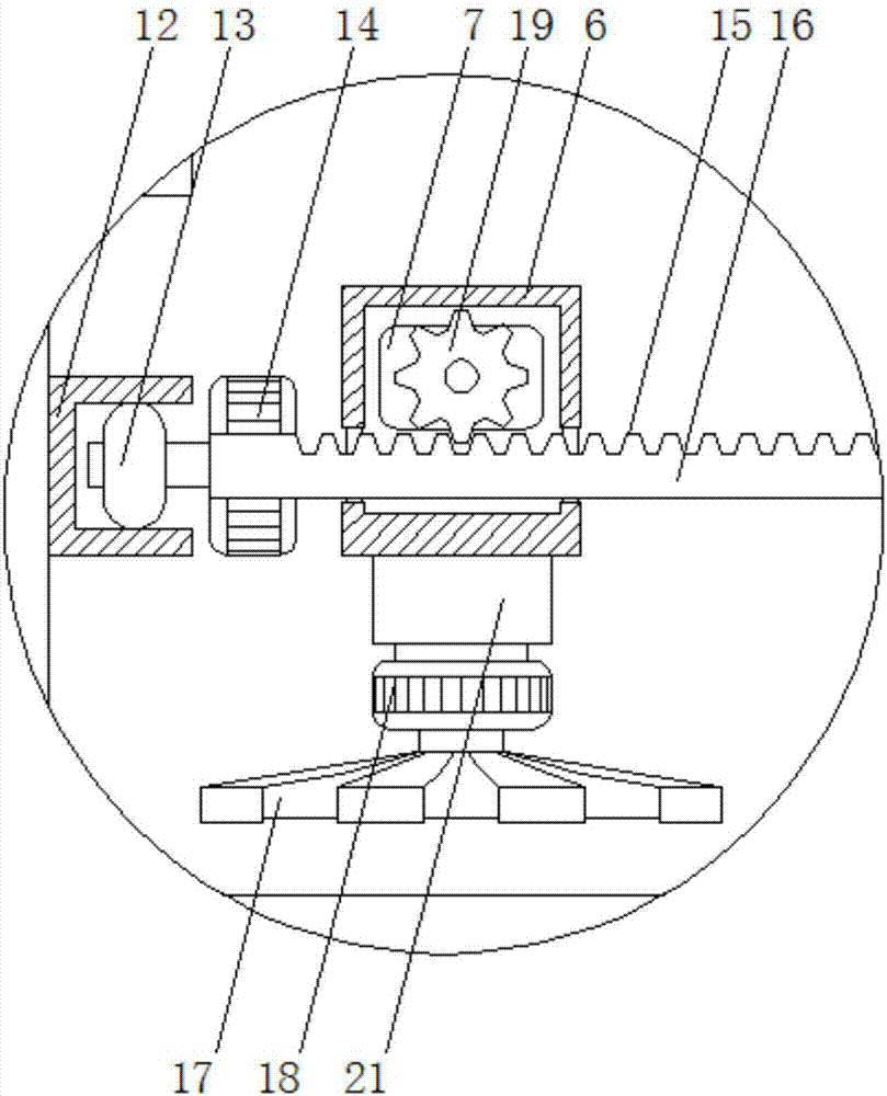
[0031] see Figure 1-5 , the present invention provides a technical solution: a CNC machine tool cleaning device, including a CNC machine tool 1, a vibrating motor box 4, a machine tool base 11 and a slide rail 16, the CNC machine tool 1 is fixedly installed on the top of the machine tool base 11, and the CNC machine tool A control panel 2 is fixedly installed on the outer wall of one end of the machine tool 1, and a sliding door 9 is slidably installed on the...


PUM


Abstract

The invention discloses a cleaning device for a numerically controlled machine tool, which comprises a numerically controlled machine tool, a vibrating motor box, a machine base and a slide rail. A numerically controlled machine tool is fixedly installed on the top of the machine tool base, and a control panel is fixedly installed on the outer wall of one end side of the numerically controlled machine tool. A sliding door is slidably installed on the outer wall of the other end of the CNC machine tool, and a processing room is fixed in the middle of the CNC machine tool, and the sliding door is matched with the processing room, and the center of the inner wall on both sides of the processing room is respectively movably installed with a processing tool; The inner walls on both sides of the processing chamber are located on the top of the processing tool and are fixed with a vibrating motor box by screws. The vibrating motor box is fixed with a vibrating motor inside. The present invention cleans the CNC machine tool by using the cleaning method of electromagnet adsorption, avoiding the traditional The damage caused to the mechanical equipment by using the flushing cleaning method, and the invention can clean the equipment when the equipment is working, without affecting the production efficiency of the numerical control machine tool.

Description

technical field [0001] The invention relates to the technical field of machine tool equipment, in particular to a cleaning device for a numerically controlled machine tool. Background technique [0002] CNC machine tool is the abbreviation of Computer numerical control machine tools, which is an automatic machine tool equipped with a program control system. The control system can logically process programs with control codes or other symbolic instructions, decode them, express them in coded numbers, and input them into the numerical control device through the information carrier. After calculation and processing, various control signals are sent by the numerical control device to control the movement of the machine tool, and the parts are automatically processed according to the shape and size required by the drawing. [0003] CNC machine tools can effectively reduce the processing time and auxiliary time of parts. The range of sound speed and feed rate of the spindle of CN...

Claims


Application Information

Patent Timeline
IPC IPC(8): B23Q11/00
CPCB23Q11/0064
Inventor 钱春利
Owner 苏州圣凡自动化科技有限公司
Learn More