Hydro-pneumatic suspension hydraulic system

A hydraulic system and oil-pneumatic suspension technology, which is applied in the field of oil-pneumatic suspension hydraulic system and oil-pneumatic suspension, can solve problems such as limiting off-road speed, limiting system performance, and harsh riding environment for occupants, so as to avoid hitting limiters, improve heat dissipation conditions, and improve The effect of vibrating environment

Active Publication Date: 2017-11-24
CHANGAN UNIV
View PDF3 Cites 5 Cited by
  • Summary
  • Abstract
  • Description
  • Claims
  • Application Information

AI Technical Summary

Problems solved by technology

Therefore, the nonlinear stiffness and damping characteristics of a good oil-pneumatic suspension can make the vehicle have good ride comfort and off-road performance, which is difficult to achieve with traditional passive suspensions.
Although the oil-air suspension has obvious advantages compared with other suspension forms, it still belongs to the traditional passive suspension category. Once the damping parameters are selected, they cannot be changed. From the perspective of vehicle comfort and handling stability, only A compromise solution can be adopted for different road conditions, which limits the full performance of the system and causes the following problems in the existing oil-air suspension:
Under bad road conditions, the damping parameters of the oil-pneumatic suspension cylinders have been selected and cannot be changed, resulting in a large vibration acceleration at the center of mass of the vehicle and the driver, which limits the

Method used


Image

  • Hydro-pneumatic suspension hydraulic system
  • Hydro-pneumatic suspension hydraulic system

Examples


Embodiment Construction

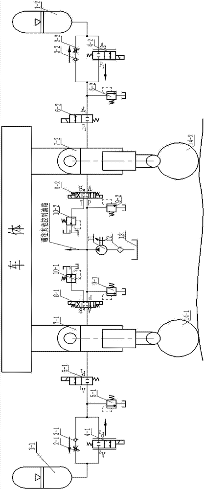
[0022] Such as figure 1 As shown, the present invention discloses an oil-pneumatic suspension hydraulic system, which includes an oil-pneumatic spring and a hydraulic control element. The hydraulic control element includes a first overflow valve, a two-position two-way electromagnetic reversing valve, a three-position four-way electromagnetic reversing valve, a second overflow valve, a back pressure valve, a hydraulic pump 11, a filter 12 and Oil tank 13; among the oil-gas spring and the hydraulic control element, all other components except the suspension cylinder are arranged inside the automobile, and the components are connected through hydraulic oil pipes. In this embodiment, two sets of hydraulic systems are provided, that is, a pair of oil-pneumatic springs and hydraulic control elements are provided, respectively acting on the wheels on both sides of the same axle. The pair of hydraulic control elements share an oil tank 13 , a filter 12 and a hydraulic pump 11 . The...


PUM


Abstract

The invention discloses a hydro-pneumatic suspension hydraulic system. The hydro-pneumatic suspension hydraulic system comprises hydro-pneumatic springs and hydraulic control elements; each hydro-pneumatic spring comprises an energy accumulator, a throttle valve and the like; and each hydraulic control element comprises a backpressure valve, a hydraulic pump, a filter, an oil tank and the like. According to the characteristics of nonlinearity, variable stiffness, variable damping and the like of the hydro-pneumatic suspension system, single-way valves, the throttle valves and two-position two-way electro proportional valves are arranged outside suspension cylinders correspondingly, the positions of valve cores are changed by controlling the electric current flowing through the two-position two-way electro proportional valves, further the through-flow areas of valve openings are changed, and accordingly the size of damping can be adjusted timely according to the road surface roughness, and the smoothness and the control stability of a vehicle are improved to reach optimum matching so that semi-active control over a hydro-pneumatic suspension can be achieved easily; and meanwhile, the functions of adjusting the vehicle attitude, shutting the vehicle and the like can be achieved by controlling opening and closing of two-position two-way electromagnetic reversing valves and three-position four-way electromagnetic reversing valves, and accordingly the trafficability of the integral vehicle is improved, and the different requirements for rigid operation and flexible driving are met.

Description

technical field [0001] The invention relates to the technical field of automobiles, and relates to oil-pneumatic suspension technology, in particular to an oil-pneumatic suspension hydraulic system for vehicles such as off-road vehicles. Background technique [0002] Suspension (suspension) is one of the important assemblies of modern vehicles, and it is the general term for all force transmission connection devices between the frame (or load-bearing body) and the axle (or wheel). Its function is to transmit the vertical reaction force (supporting force), longitudinal reaction force (traction and braking force) and lateral reaction force of the road surface on the wheel, as well as the moment caused by these reaction forces, to the frame (or load bearing). type body) to ensure the normal running of the vehicle. [0003] Oil-pneumatic suspension has good nonlinear damping characteristics, simple structure and reliable performance, and has been widely used in heavy-duty vehic...

Claims


Application Information

Patent Timeline
IPC IPC(8): B60G11/26B60G11/30
CPCB60G11/26B60G11/30B60G2202/154
Inventor 马登成李平李宗
Owner CHANGAN UNIV
Why Eureka
Try Eureka