
Battery pop-up system of charging station

A charging station and battery technology, applied in charging stations, battery pack components, battery circuit devices, etc., can solve the problems of severe combustion of lithium batteries and difficult fire fighting methods, and achieve simple and reasonable structure, meet fire protection needs, and operate reliable results

Pending Publication Date: 2017-11-24
常州市三利精机有限公司
View PDF9 Cites 10 Cited by
  • Summary
  • Abstract
  • Description
  • Claims
  • Application Information

AI Technical Summary

Problems solved by technology

[0004] However, the existing container-type charging stations have fire hazards. If a battery in the charging station explodes and catches fire due to a fault, it will easily spread to other batteries in the station, causing a chain effect, and the fire will spread to the entire station in a short period of time.
Moreover, when the on-board energy storage battery is a lithium battery, the fire of the fully charged lithium battery burns violently, and it is difficult to quickly and effectively extinguish it with existing fire-fighting methods.

Method used


Image

  • Battery pop-up system of charging station
  • Battery pop-up system of charging station
  • Battery pop-up system of charging station

Examples


Embodiment 1

[0031] Example 1, such as figure 1 , 2 , 3, 4, 5, 6, 7, 8, 9, 10 and 11:

[0032] This embodiment 1 can be applied to the battery directly entering the charging compartment for charging, and can also be applied to the battery being placed in the charging tray and entering the charging compartment for charging. In this embodiment 1, the battery is placed in the charging tray and entered into the charging compartment for charging as an example. Be explained:

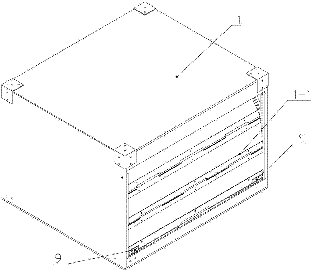
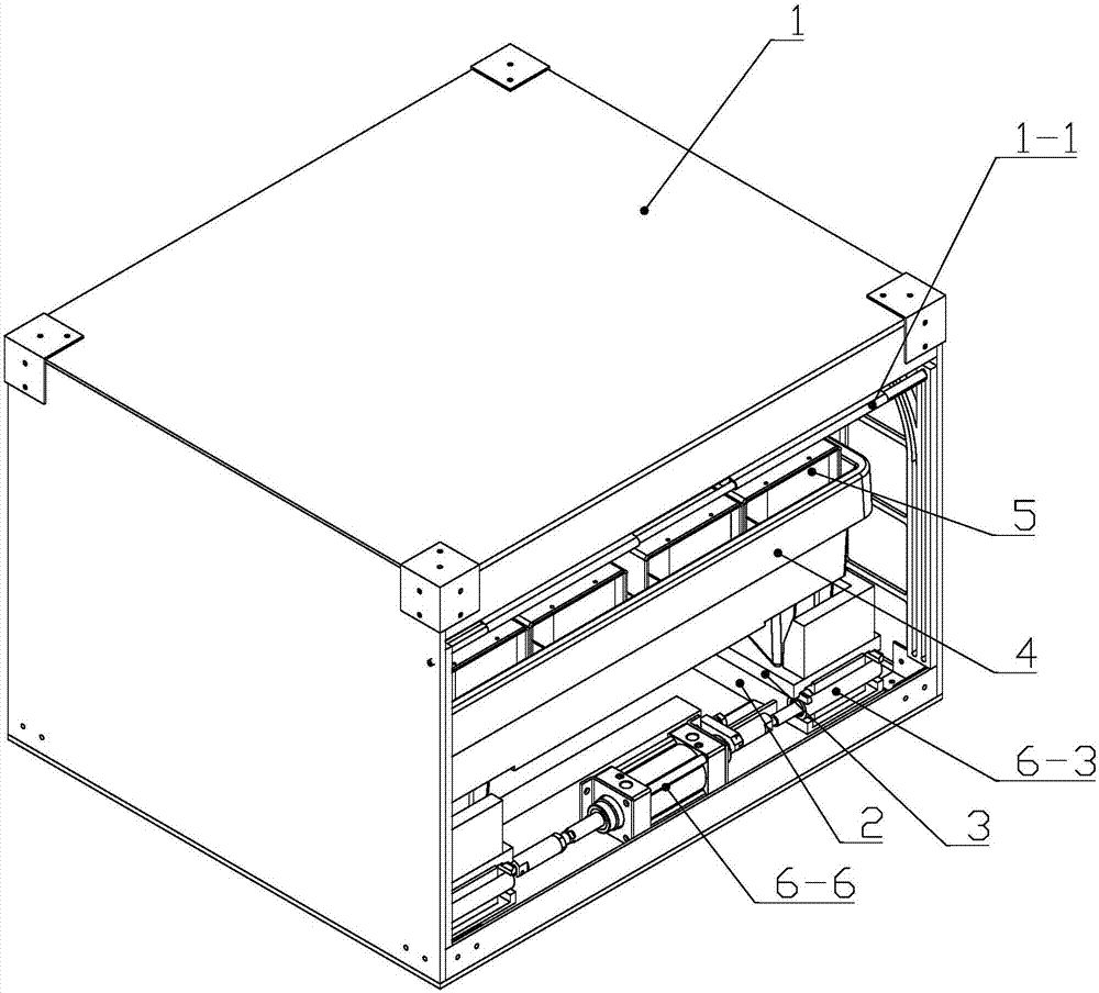
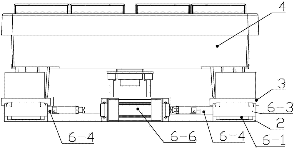
[0033] A battery ejection system for a charging station, comprising a battery ejection device, an ejection seat 2, a slide seat 3 and a connector separation device, there are two battery ejection devices, which are respectively located on the left and right sides of the bottom of the charging compartment 1, and are installed on the corresponding In the ejection seat 2 on the side, the connector separation device is arranged between the ejection seats 2 on the left and right sides. The battery 5 is placed in the charging...

Embodiment 2

[0057] Compared with Embodiment 1, the difference is that the sliding seat 3 is omitted, the charging tray 4 is directly seated on the ejection seat 2, and is guided by the ejection seat 2 like the sliding seat 3, and the ejection block 6-1 directly acts on the charging on tray 4.

Embodiment 3

[0059] Compared with Embodiment 2, the ejection seat 2 is further omitted, and the ejection block 6-1 and the charging tray 4 are guided to slide forward and backward in a straight line through respective guide structures such as slide rails and guide posts.


PUM


Abstract

The invention relates to a battery pop-up system of a charging station. The battery pop-up system of the charging station comprises a battery pop-up device; the battery pop-up device comprises an energy storage elastic part, a pop-up block and a release device; the release device locks the pop-up block at the energy storage position of the energy storage elastic part; the energy storage elastic part pops up the battery through the pop-up block; the release device comprises a lock sleeve, a lock shaft, a rolling ball and an actuator; the lock sleeve is fixed relative to a charging cabin; the lock shaft is inserted into the lock sleeve; the lock sleeve is provided with a rolling ball hole; the rolling ball is embedded into the rolling ball hole; the lock shaft adopts a two-section type and is divided into a large-diameter section and a small-diameter section; when the pop-up block is in an initial locking state, the lock sleeve is embedded into a locking port of the pop-up block, the large-diameter section of the lock shaft pushes out the rolling ball, the rolling ball is embedded into a rolling ball groove in the locking port of the pop-up block, and the rolling ball clamped between the pop-up block and the lock shaft locks the pop-up block and the lock shaft. The battery pop-up system of the charging station has the beneficial effects of simple and reasonable structure, reliable action, starting quickness and capability of meeting the firefighting requirement by popping up the battery.

Description

technical field [0001] The present invention relates to a battery ejection system for a charging station. Background technique [0002] Compared with traditional fuel vehicles, electric vehicles use vehicle-mounted energy storage batteries as energy sources and motors to drive the wheels. Compared with traditional fuel vehicles, the on-board energy storage batteries of electric vehicles take a long time to charge online and the cruising range is short, which greatly restricts the use of electric vehicles. By directly replacing the on-board energy storage battery, the electric energy replenishment time of the electric vehicle can be greatly shortened. If a battery car battery replacement station is specially built for the replacement of vehicle-mounted energy storage batteries, the cost will be high and the land utilization rate will be low. For this reason, a container-type charging station has been developed in the prior art, such as the energy storage battery container di...

Claims


Application Information

Patent Timeline
Patent Type & Authority Applications(China)
IPC IPC(8): B60L11/18H02J7/00H01M2/10H01M50/20
CPCH02J7/0045B60L53/30H02J7/00H01M50/20Y02T10/70Y02T90/12Y02T10/7072Y02E60/10
Inventor 吴光辉陈立新谈言周国新
Owner 常州市三利精机有限公司
Learn More