Biomass pyrolysis device for laboratory

A technology for biomass pyrolysis and laboratory use, applied in the field of laboratory biomass pyrolysis devices, can solve problems such as low reaction efficiency, uneven temperature, complex structure, etc., achieve uniform material temperature, simple device structure, and high energy efficiency. The effect of low consumption

Inactive Publication Date: 2017-11-24
KUNMING UNIV OF SCI & TECH
View PDF5 Cites 0 Cited by
  • Summary
  • Abstract
  • Description
  • Claims
  • Application Information

AI Technical Summary

Problems solved by technology

[0004] The invention provides a laboratory biomass pyrolysis device, which is used to solve the problems of uneven temperature, complex structure, low reaction efficiency and high energy consumption of existing devices

Method used


Image

  • Biomass pyrolysis device for laboratory
  • Biomass pyrolysis device for laboratory
  • Biomass pyrolysis device for laboratory

Examples


Embodiment 1

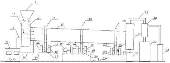
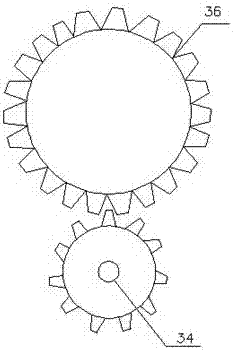
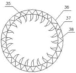
[0015] Embodiment 1: as Figure 1-3 As shown, a laboratory biomass pyrolysis device includes a feed hopper 1, a front sealing cover 2, a feed pipe 3, a thermocouple 4, a temperature controller 5, an electric wire 6, a large gear I7, a support frame I8, Platform Ⅰ9, drum 10, shaft Ⅰ11, support frame Ⅱ12, left support wheel 13, large gear Ⅱ14, motor 15, gearbox 16, support frame Ⅲ17, support frame Ⅳ18, rotating shaft 19, drive wheel 20, platform Ⅱ21, right support Wheel 22, support frame Ⅴ23, platform Ⅲ24, gear wheel Ⅲ25, shaft Ⅱ26, support frame Ⅵ27, outlet pipe 28, rear sealing cover 29, solid product tank 30, liquid product tank 31, water cooling pipe 32, gas product tank 33, round Hole 34, supporting plate 35 and heating resistance wire 38;

[0016] The feed hopper 1 is connected to the feed pipe 3, and the feed pipe 3 extends into the drum 10 through the front sealing cover 2, the front sealing cover 2 is fixed, and is sealed with one end of the drum 10; the rear sealing c...

Embodiment 2

[0020] Embodiment 2: as Figure 1-3 As shown, a laboratory biomass pyrolysis device includes a feed hopper 1, a front sealing cover 2, a feed pipe 3, a thermocouple 4, a temperature controller 5, an electric wire 6, a large gear I7, a support frame I8, Platform Ⅰ9, drum 10, shaft Ⅰ11, support frame Ⅱ12, left support wheel 13, large gear Ⅱ14, motor 15, gearbox 16, support frame Ⅲ17, support frame Ⅳ18, rotating shaft 19, drive wheel 20, platform Ⅱ21, right support Wheel 22, support frame Ⅴ23, platform Ⅲ24, gear wheel Ⅲ25, shaft Ⅱ26, support frame Ⅵ27, outlet pipe 28, rear sealing cover 29, solid product tank 30, liquid product tank 31, water cooling pipe 32, gas product tank 33, round Hole 34, supporting plate 35 and heating resistance wire 38;

[0021] The feed hopper 1 is connected to the feed pipe 3, and the feed pipe 3 extends into the drum 10 through the front sealing cover 2, the front sealing cover 2 is fixed, and is sealed with one end of the drum 10; the rear sealing c...


PUM


Abstract

The invention relates to a biomass pyrolysis device for a laboratory. The biomass pyrolysis device for the laboratory comprises a feed hopper, a front sealing cover, a feeding pipe, a thermocouple, a temperature controller, a wire, a large gear I, a supporting frame I, a platform I, a rotary drum, a shaft I, a supporting frame II, a left supporting wheel, a large gear II, a motor, a gearbox, a supporting frame III, a supporting frame IV, a rotary shaft, a driving wheel, a platform II, a right supporting wheel, a supporting frame V, a platform III, a large gear III, a shaft II, a supporting frame VI, an outlet pipe, a back sealing cover, a solid product tank, a liquid product tank, a water cooling pipe, a gas product tank, a round hole, a supporting plate and a heating resistance wire. As for the biomass pyrolysis device for the laboratory, through inclination design of the rotary drum, a material can automatically move toward an outlet; through the design of the supporting plate, the action of stirring the material can be exerted, so that the temperature of the material is uniform; the gearbox can regulate the speed of the rotary drum, and thus the residence time of the material is controlled; and the whole device has a simple structure and is high in efficiency and low in energy consumption.

Description

technical field [0001] The invention relates to a laboratory biomass pyrolysis device, which belongs to the technical field of chemical reaction devices. Background technique [0002] Biomass energy is an important part of renewable energy. It has the characteristics of abundant resources and low pollution. Its development and utilization have become an important research topic in the 21st century. my country is a large agricultural country with abundant biomass resources, such as straw, wheat straw, reed, bagasse, etc. are inexhaustible energy warehouses. Biomass pyrolysis technology can convert biomass raw materials into charcoal, bio-oil and combustible gas, and has become a research hotspot. Various scientific research institutions are conducting experimental analysis on different biomass raw material pyrolysis technologies and the characteristics of biomass pyrolysis products. , in order to obtain the best conditions for the pyrolysis of different biomass raw materials...

Claims


Application Information

Patent Timeline
IPC IPC(8): C10B53/02C10B47/18C10B47/30
CPCC10B47/18C10B47/30C10B53/02Y02E50/10
Inventor 吴桢芬徐建忠
Owner KUNMING UNIV OF SCI & TECH
Why Eureka
Try Eureka