Film coating system and film thickness monitoring device thereof, and film coating method and film thickness monitoring method thereof

A monitoring device and coating system technology, applied in sputtering coating, ion implantation coating, vacuum evaporation coating and other directions, can solve the problems of short use time and frequent replacement of quartz crystal oscillators, and achieve extended continuous operation time, The effect of avoiding uneven thickness and reducing costs

Inactive Publication Date: 2017-11-24
茆胜
View PDF4 Cites 12 Cited by
  • Summary
  • Abstract
  • Description
  • Claims
  • Application Information

AI Technical Summary

Problems solved by technology

[0004] The technical problem to be solved by the present invention is to provide a coating system and its film thickness monitoring device, and a coating method and its film thickness monitoring method in view of the defects of short service life and frequent replacement of quartz crystal oscillators in the prior art

Method used


Image

  • Film coating system and film thickness monitoring device thereof, and film coating method and film thickness monitoring method thereof
  • Film coating system and film thickness monitoring device thereof, and film coating method and film thickness monitoring method thereof
  • Film coating system and film thickness monitoring device thereof, and film coating method and film thickness monitoring method thereof

Examples


Embodiment Construction

[0025] In order to make the object, technical solution and advantages of the present invention clearer, the present invention will be further described in detail below in conjunction with the accompanying drawings and embodiments. It should be understood that the specific embodiments described here are only used to explain the present invention, not to limit the present invention.

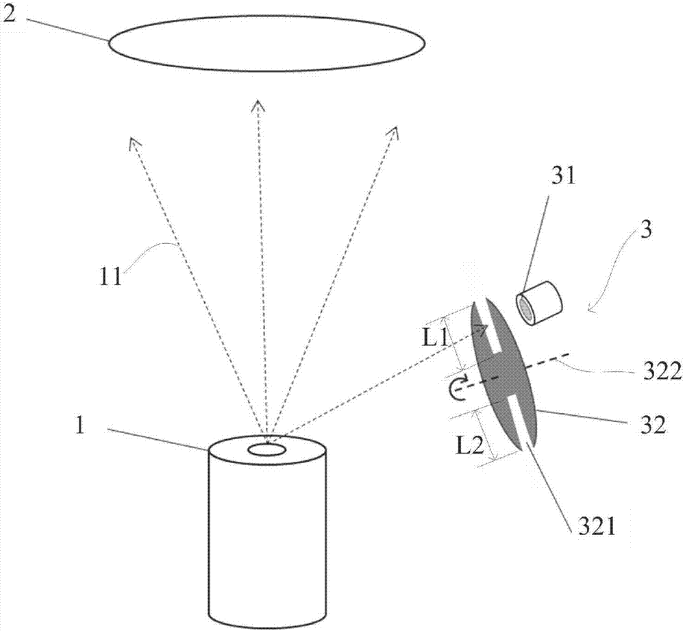
[0026] see figure 1 , figure 1 A schematic structural view of a coating system according to an embodiment of the present invention is shown, the coating system includes a coating source 1 , a substrate 2 , and a film thickness monitoring device 3 . The coating source 1 generates a gas flow 11 of a coating material, and the gas flow 11 deposits a desired film on the substrate 2 , and the film thickness monitoring device 3 is used to monitor the thickness of the film coated on the substrate 2 .

[0027] In a specific implementation of this embodiment, the coating source 1 includes a crucible, and t...


PUM


Abstract

The invention relates to a film coating system and a film thickness monitoring device thereof, and a film coating method and a film thickness monitoring method thereof. The film thickness monitoring device comprises a shielding plate and a quartz crystal wafer, wherein the shielding plate and the quartz crystal wafer can rotate relative to each other, and the shielding plate is provided with an opening; and in the relative rotating process, the opening allows airflow of a film coating material to pass through to enable the airflow to reach the quartz crystal wafer, and other parts, except the opening, of the shielding plate block the airflow from reaching the quartz crystal wafer. The shielding plate is adopted for blocking the airflow, the deposition velocity of film on the quartz crystal wafer is slowed down, the service time of the quartz crystal wafer is prolonged, and therefore the continuous running time of the equipment is prolonged, and the cost is correspondingly reduced. In addition, the shielding plate and the quartz crystal wafer can rotate relative to each other, so that the airflow of the film coating material can pass through the opening in the rotating process and then is uniformly deposited on the quartz crystal wafer, the situation that the thickness of the film coating materials deposited on the quartz crystal wafer is not uniform due to the fact that the opening is arranged is avoided, and the monitoring accuracy is guaranteed and improved.

Description

technical field [0001] The invention relates to the field of film coating, in particular to a film coating system and a film thickness monitoring device thereof, a film coating method and a film thickness monitoring method thereof. Background technique [0002] In the field of vacuum coating, the quartz crystal oscillation monitoring method is the most commonly used method to monitor the film thickness and material evaporation rate during the process. The quartz crystal oscillation monitoring method mainly utilizes the piezoelectric effect and mass load effect of the quartz crystal. When a thin film is deposited on the surface of the crystal oscillator, the vibration of the crystal will weaken. This reduction in amplitude or frequency is caused by the deposited thin film. The thickness and density of the film are determined by using very sophisticated electronic equipment to test the change of vibration multiple times per second, so as to realize real-time monitoring of the ...

Claims


Application Information

Patent Timeline
Patent Type & Authority Applications(China)
IPC IPC(8): C23C14/54
CPCC23C14/546
Inventor 茆胜
Owner 茆胜
Why Eureka
Try Eureka