Construction method for back cavity of tunnel lining and constructed composite lining structure

A construction method and composite lining technology, applied in tunnel lining, tunnel, wellbore lining and other directions, can solve the problems of increasing lining load, cracking of concrete lining, cavity expansion, etc. safe effect

Pending Publication Date: 2017-11-24
CHINA RAILWAY SHISIJU GROUP CORP
View PDF4 Cites 8 Cited by
  • Summary
  • Abstract
  • Description
  • Claims
  • Application Information

AI Technical Summary

Problems solved by technology

[0006] In the case of tunnel collapse or cement gushing, the arch of the tunnel will usually collapse. In the prior art, concrete backfill or mortar backfill is mostly used, and then sand blowing is used for filling. However, when concrete backfill or mortar backfill is used, due to the concrete Compared with the mortar itself, the weight is relatively large, which will increase the lining load, which may cause the concrete lining to break. If the chopped sand is used for filling, the cavity will expand due to water erosion, and the tunnel cavity is still a risk during the tunnel operation period.

Method used


Image

  • Construction method for back cavity of tunnel lining and constructed composite lining structure
  • Construction method for back cavity of tunnel lining and constructed composite lining structure

Examples


Embodiment 1

[0040] Embodiment 1 The construction method of the cavity behind the tunnel lining, the steps are as follows:

[0041] (1) Drill grouting holes on the lining surface, the inner diameter of the grouting holes is 40cm, the longitudinal spacing of the grouting holes is 3m, and the circumferential spacing is 3.5m;

[0042] (2) Install the grouting pipe in the grouting hole. The outer diameter of the grouting pipe is 40cm, the thickness of the grouting pipe is 3.5mm, and the length of the grouting pipe entering the back of the lining is 3.5m. Seal the grouting hole and the grouting the space between the tubes;

[0043] (3) Pour foam concrete into the cavity behind the lining through the grouting pipe to form a buffer layer to reduce the additional load on the tunnel lining;

[0044] The raw material composition of the foamed concrete, in parts by weight: 245 parts of cement, 2.1 parts of anti-cracking fiber, 2.4 parts of coagulation accelerator, 16.5 parts of foaming agent, 6 part...

Embodiment 2

[0053] Embodiment 2 The construction method of the cavity behind the tunnel lining, the steps are as follows:

[0054] (1) Drill grouting holes on the lining surface, the inner diameter of the grouting holes is 32cm, the longitudinal spacing of the grouting holes is 4m, and the circumferential spacing is 2.5m;

[0055] (2) Install the grouting pipe in the grouting hole, the outer diameter of the grouting pipe is 31.5cm, the thickness of the grouting pipe is 3mm, the length of the grouting pipe entering the back of the lining is 2m, seal the grouting hole and the grouting pipe the gap between

[0056] (3) Pour foam concrete into the cavity behind the lining through the grouting pipe to form a buffer layer to reduce the additional load on the tunnel lining;

[0057] The raw material composition of the foamed concrete, in parts by weight: 210 parts of cement, 1.6 parts of anti-cracking fiber, 2.1 parts of coagulation accelerator, 11 parts of foaming agent, 8 parts of foam stabil...

Embodiment 3

[0068] Example 3 Composite lining structure after treatment of voids behind the lining

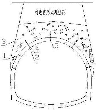
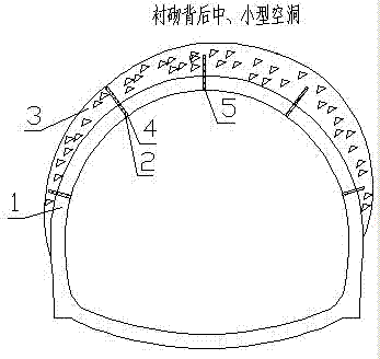
[0069] Such as figure 1 and figure 2 As shown, the composite lining structure includes a lining 1, a grouting hole 2, a grouting pipe 3, a foam concrete layer 4 and a waterproof mortar column 5, and the lining 1 is provided with a grouting hole 2, and the inner diameter of the grouting hole 2 is 40cm , the longitudinal spacing of the grouting hole 2 is 3m, the circumferential spacing is 3.5m, the grouting hole 2 is provided with a grouting pipe 3, the length of the grouting pipe 3 entering the cavity is 3.5m, and the outer diameter of the grouting pipe 3 is 40cm, the thickness of the grouting pipe is 3.5mm, the grouting hole 2 is sealed with the grouting pipe 3, the outer side of the lining 2 is a foam concrete layer 4, and the inside of the grouting pipe 3 is a waterproof mortar column 5;

[0070] When the cavity behind the lining is in the large collapse section, the minimum height of...


PUM


Abstract

The invention relates to a construction method for a back cavity of a tunnel lining and a constructed composite lining structure. The construction method comprises the following steps: drilling a grouting hole in the surface of a lining; mounting a grouting tube in the grouting hole; filling the cavity on the back of the lining with foam concrete through the grouting tube to form a buffer layer; filling cavities or a large landslide section or other road sections; closing and compacting the grouting tube by using waterproof mortar, and enabling the surface of the grouting tube to be level and parallel to the lining. According to the composite lining structure formed after construction, the grouting hole is formed in the lining, the grouting tube is arranged in the grouting hole, the length of a part, which enters the cavity, of the grouting tube is 1-4 m, the grouting hole and the grouting tube are hermetically combined in a sleeving manner, the outer side of the lining is a foam concrete layer, and a waterproof mortar column is arranged in the grouting tube. By the construction method, impact of stones falling from the top of the cavity to the lining is reduced effectively, and the safety of the lining structure is guaranteed.

Description

technical field [0001] The invention relates to a construction method for a cavity behind a tunnel lining and a composite lining structure after construction, and belongs to the technical field of tunnel construction. Background technique [0002] Due to the corrosiveness of groundwater, the tunnel lining concrete deteriorates, especially in the area where the seepage water develops, which is deeply corroded and becomes loose and crystalline; when the corrosion medium in the tunnel environment is mainly calcium sulfate, it has a crystalline erosion effect on the concrete, and groundwater and The contact of the lining leads to the loosening of the concrete, the gradual decrease in strength, the development of seepage water, and the gradual deposition of sulfate on the surface of the lining in the water, resulting in the gradual deterioration of the lining. The formation of voids behind the lining is mainly due to three reasons: [0003] (1) The construction of the tunnel was...

Claims


Application Information

Patent Timeline
Patent Type & Authority Applications(China)
IPC IPC(8): E21D9/00E21D11/10
CPCE21D9/002E21D11/10
Inventor 李占先周建芳顾博渊党双宝丛义营梁万波李庭荟周华阳杨伟辉
Owner CHINA RAILWAY SHISIJU GROUP CORP
Why Eureka
Try Eureka