Multi-LNG tank box synchronous filling system

A filling system and tank container technology, applied in the field of LNG transportation, can solve the problem of inability to synchronously and quickly fill multiple LNG tank containers.

Active Publication Date: 2017-11-24
SUZHOU CYPAG HYDRO TECH CO LTD +1
View PDF11 Cites 0 Cited by
  • Summary
  • Abstract
  • Description
  • Claims
  • Application Information

AI Technical Summary

Problems solved by technology

However, when there are multiple LNG tanks on the transport ship, the existing loading and unloading methods cannot realize simultaneous and rapid filling of multiple LNG tanks

Method used


Image

  • Multi-LNG tank box synchronous filling system
  • Multi-LNG tank box synchronous filling system
  • Multi-LNG tank box synchronous filling system

Examples


Embodiment 1

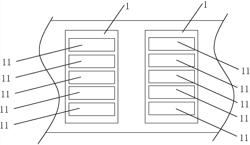
[0048] Embodiment 1: as figure 1 and figure 2 As shown, a multi-LNG tank container 11 synchronous filling system includes a plurality of LNG tank containers 11 ( figure 1 is a top view), the purpose of the present invention is to realize synchronous filling of multiple LNG tanks 11 .

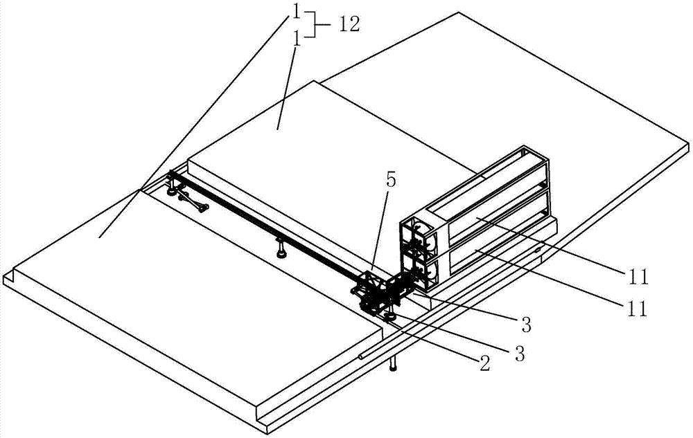
[0049] Such as figure 1 and figure 2 As shown, the storage module 12 of the LNG tank 11 includes a platform 1 arranged on a plane, and the LNG tank 11 on the relative platform 1 is oppositely arranged, and the LNG tank 11 is arranged side by side along its own width direction. figure 2 In order to show clearly, the LNG tanks 11 arranged side by side are hidden); in the height direction, the LNG tanks 11 are stacked in two layers; in the length direction of the platform 1, multiple groups of LNG storage tanks can also be arranged.

[0050] Such as figure 2 As shown, the system includes a main pipe 2 for transporting LNG and returning gas, and an automatic docking device 3 for realizing a...

Embodiment 2

[0068] Embodiment 2: as Figure 11 As shown, a kind of LNG tank carrier includes a deck 7, and the multi-LNG tank synchronous filling system in Embodiment 1 is arranged on the deck 7, while the LNG storage module 12 is arranged on the deck 7, and the third oil cylinder 55 The main body can be arranged below deck 7, and the piston rod of the third oil cylinder 55 can pass through deck 7 and be positioned at deck 7 Figure 10 The lifting platform 54 described in is connected.

[0069] The working principle of embodiment 2 is the same as that of embodiment 1. The LNG receiving station or liquefaction factory wharf injects low-pressure LNG into the main pipe 2 through the crane pipe, so as to realize the synchronous filling of multiple LNG tank containers 11 on the LNG tank container transport ship. .

Embodiment 3

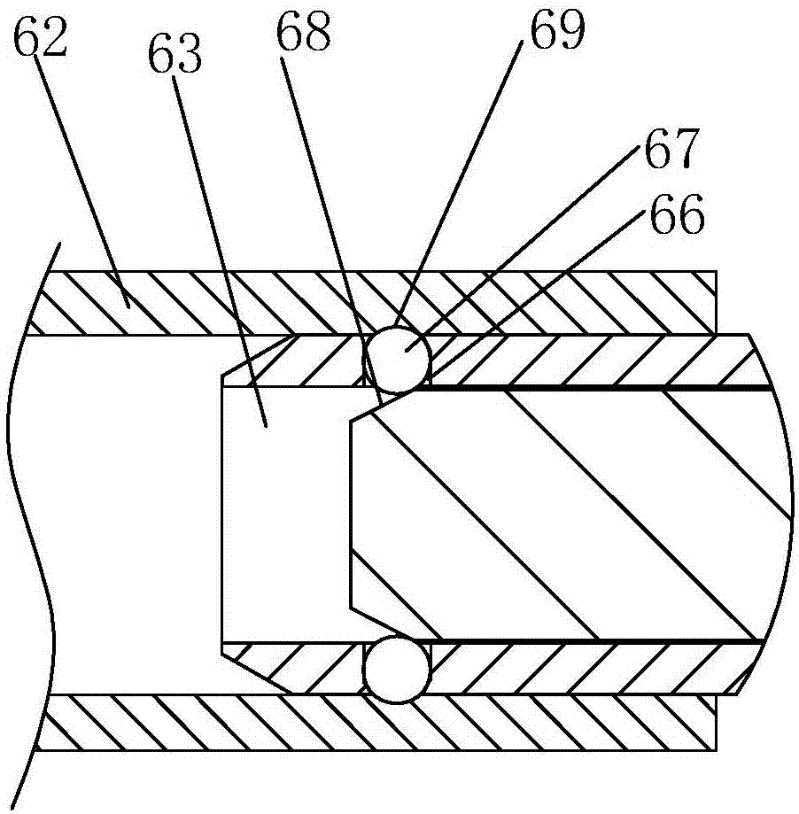
[0070] Embodiment 3: as Figure 12 as shown, Figure 11 It is a cross-sectional schematic diagram of the female filling joint 17. A vacuum temperature insulating cavity 74 is arranged in the inner wall of the female filling joint 17, and the vacuum temperature insulating cavity 74 is arranged around the female filling joint 17. By setting the vacuum temperature insulating cavity 74 , and then the low-pressure LNG at minus 100 degrees in the male filling joint 32 will not cause the outer surface of the male filling joint 32 to freeze during the filling process, so that the male filling joint 32 can be better inserted into the above-mentioned female filling Within the joint 17, the problem of wear is reduced.

[0071] A one-way valve is arranged in the female filling joint 17. When the above-mentioned male filling joint 32 is inserted into the female filling joint 17, the above-mentioned male filling joint 32 pushes the spool 71 to move backward, and the valve core 71 in the ma...


PUM


Abstract

The invention discloses a multi-LNG tank box synchronous filling system. The multi-LNG tank box synchronous filling system comprises a header pipe, branch pipes and LNG tank boxes. The header pipe communicates with a liquid feeding end and a return air end. The header pipe communicates with one ends of the multiple branch pipes, the other end of each branch pipe is provided with a filling end, each filling end is correspondingly provided with one LNG tank box in the same plane, each LNG tank box is provided with a receiving end, and an automatic docking device is arranged between the filling end of each branch pipe and the corresponding receiving end. Through the automatic docking device, communication between each filling end and the corresponding receiving end is achieved, in other words, multiple tank bodies can be filled synchronously through the header pipe, and the requirement for filling the multiple tank boxes on a ship is met; and the LNG tank boxes on an LNG tank box transport ship can be filled with the LNG in a gas field liquefaction factory directly, and after the LNG tank box transport ship is unloaded in a dangerous goods area of a container wharf, the tank boxes can be transported through a flat car or the railway directly.

Description

technical field [0001] The invention relates to the field of LNG transportation, in particular to a synchronous filling system for multiple LNG tanks. Background technique [0002] LNG is the abbreviation of liquefied natural gas. As a clean energy source, in terms of import, it helps energy consuming countries to diversify their energy supply; in terms of export, it helps natural gas producing countries to effectively develop natural gas resources , Increase foreign exchange income, and promote national economic development. [0003] The coastal LNG projects currently being planned and implemented in China include: Guangdong, Fujian, Zhejiang, Shanghai, Jiangsu, Shandong, Liaoning, Ningxia, Tangshan, Hebei, etc., which will eventually form a coastal LNG receiving station and pipeline network. [0004] The existing conventional LNG medium and long-distance transportation is completed by bulk ships from the gas field liquefaction plant to the coastal LNG receiving station, a...

Claims


Application Information

Patent Timeline
Patent Type & Authority Applications(China)
IPC IPC(8): F17C5/02F17C5/00F17C13/00
CPCF17C5/002F17C5/02F17C13/00F17C2270/0105
Inventor 张冲霍志亮徐龙魏崇光陈斌
Owner SUZHOU CYPAG HYDRO TECH CO LTD
Why Eureka
Try Eureka