Carbon dioxide heat pump circulation loop

A technology of heat pump circulation loop and carbon dioxide, which is applied in the direction of fluid circulation arrangement, gas circulation refrigerator, refrigeration and liquefaction, etc. It can solve the problems that the critical temperature cannot be guaranteed, the throttling evaporation cannot be realized, and the carbon dioxide refrigerant cannot be condensed into a liquid state, etc.

Pending Publication Date: 2017-11-24
GUANGDONG NEW ENERGY TECH DEV
View PDF6 Cites 2 Cited by
  • Summary
  • Abstract
  • Description
  • Claims
  • Application Information

AI Technical Summary

Problems solved by technology

However, as a refrigerant, carbon dioxide has a low critical temperature (31°C), and the system needs to work in a supercritical state. Under normal circumstances, it is difficult for a water cooler to directly cool the high-temperature and high-pressure carbon dioxide refrigerant into a liquid state. The use of low-temperature cooling water (below 31°C) can condense high-temperature and high-pressure carbon dioxide refrigerant into a liquid state, but the temperature of heat pump cooling water or circulating water and the ambient temperature cannot ensure that it is lower than the critical temperature of carbon dioxide refrigerant throughout the year
Therefore, the water cooler cannot ensure that the carbon dioxide refrigerant can be condensed into a liquid state under any circumstances, and if the carbon dioxide refrigerant is not condensed into a liquid state before entering the throttling device, the purpose of throttling evaporation cannot be achieved

Method used


Image

  • Carbon dioxide heat pump circulation loop

Examples


Embodiment Construction

[0020] In order to make the object, technical solution and advantages of the present invention clearer, the present invention will be further described in detail below in conjunction with the accompanying drawings and embodiments. It should be understood that the specific embodiments described here are only used to explain the present invention, not to limit the present invention.

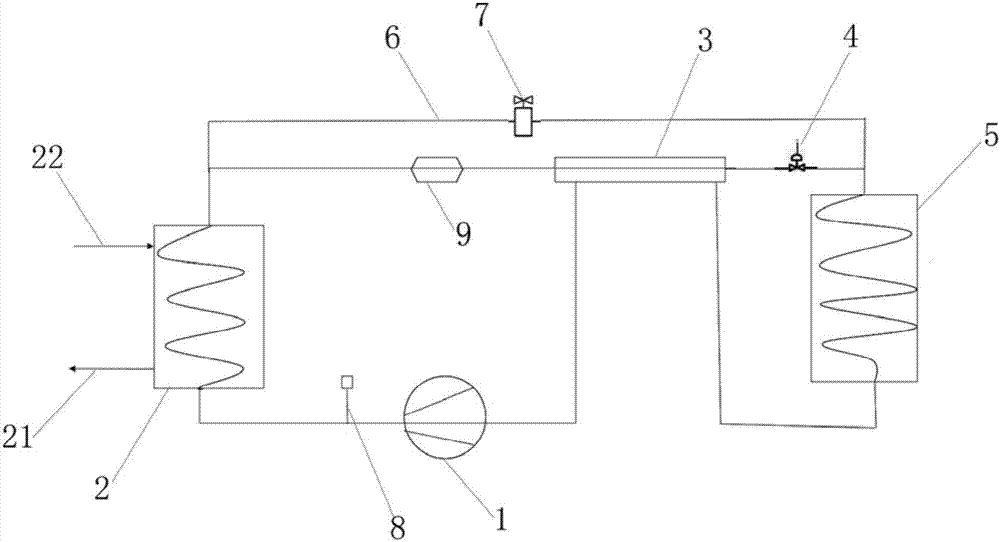
[0021] Such as figure 1 As shown, a carbon dioxide heat pump circulation circuit includes a compressor 1, a water cooling heat exchanger 2, a casing heat exchanger 3, a throttling device 4, and an evaporator 5. The above-mentioned components are connected as follows through pipelines: compressor 1 The outlet of the water cooling heat exchanger 2 is connected to the inlet of the refrigerant pipe, the outlet of the refrigerant pipe of the water cooling heat exchanger 2 is connected to the pipe side inlet of the casing heat exchanger 3, and the inlet of the cooling water pipe of the water cooling heat...


PUM


Abstract

The invention belongs to the field of air energy heat pumps or air energy water heaters, and particularly relates to a carbon dioxide heat pump circulation loop which comprises a compressor, a water cooling heat exchanger, a double-tube heat exchanger, a throttling device and an evaporator. An outlet of the compressor, a refrigerant tube of the water cooling heat exchanger, a tube pass of the double-tube heat exchanger, the throttling device, the evaporator, a shell pass of the double-tube heat exchanger and an inlet of the compressor are sequentially connected, carbon dioxide refrigerants of the water cooling heat exchanger are led into the double-tube heat exchanger, low-temperature carbon dioxide gas at an outlet of the evaporator is led into the shell pass of the double-tube heat exchanger and used for cooling the carbon dioxide refrigerants in the tube pass, the carbon dioxide refrigerants are liquefied, and the liquefied carbon dioxide refrigerants enter the throttling device and enter the inside of the evaporator after throttling pressure reduction, so that circulation of the carbon dioxide heat pump circulation loop is realized.

Description

technical field [0001] The invention belongs to the field of air energy heat pumps or air energy water heaters, in particular to a carbon dioxide heat pump circulation loop. Background technique [0002] Heat pump technology has developed rapidly in recent years, especially in northern China, it is the general trend to replace traditional coal-fired heating with air source heat pumps. At present, most of the heat pump compressors use R22, R410a and other refrigerants. Under the low temperature environment (-25°C), such compressors not only need to use gas injection to increase enthalpy or liquid injection technology to ensure sufficient exhaust temperature for heating or hot water. use, and not environmentally friendly. Carbon dioxide refrigerant is currently the most environmentally friendly refrigerant known in the world, and its physical properties are also one of the most suitable refrigerants for low-temperature heat pump systems. Carbon dioxide refrigerant has a low e...

Claims


Application Information

Patent Timeline
Patent Type & Authority Applications(China)
IPC IPC(8): F25B9/00F25B47/02F25B41/04F25B41/20
CPCF25B9/008F25B47/022F25B2347/02F25B2400/05F25B2309/06F25B41/20
Inventor 赵密升李建国李凡
Owner GUANGDONG NEW ENERGY TECH DEV
Why Eureka
Try Eureka