
Rapid detection method of tail current of current transformer

A technology of current transformer and trailing current, which is applied in the direction of measuring current/voltage, measuring only current, instruments, etc. It can solve the problems of poor low-frequency DC component filtering effect and unsatisfactory detection speed of CT tailing current, etc., so as to reduce operation risk effect

Active Publication Date: 2017-11-24
长园深瑞继保自动化有限公司
View PDF5 Cites 3 Cited by
  • Summary
  • Abstract
  • Description
  • Claims
  • Application Information

AI Technical Summary

Problems solved by technology

However, this method has poor filtering effect on low-frequency DC components.
Based on the detection method of the CT tailing current mentioned above, some literatures propose an improved full-cycle Fourier algorithm, which uses the Mann-Morrison algorithm to improve the calculation of the imaginary part. This algorithm can basically ensure that the DC component is completely filtered within 25ms after the fault is removed. However, there is still the disadvantage that the detection speed of CT tail current is not ideal

Method used


Image

  • Rapid detection method of tail current of current transformer
  • Rapid detection method of tail current of current transformer
  • Rapid detection method of tail current of current transformer

Examples


Embodiment Construction

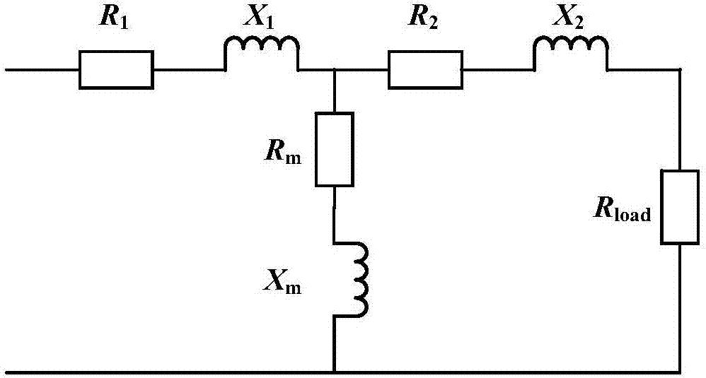
[0046] The present invention will be described in further detail below in conjunction with the accompanying drawings and embodiments. Such as figure 1 As shown, the structure of the current transformer CT is similar to that of a common transformer. For the convenience of analysis, the current transformer is converted into a T-shaped equivalent circuit, where R 1 Indicates the leakage resistance of the transformer (CT) primary side winding, X 1 is the leakage reactance of the transformer primary winding, R 2 is the leakage resistance of the secondary winding of the transformer, X 2 is the leakage reactance of the secondary winding of the transformer, R m is the magnetizing resistance of the transformer, X m is the magnetizing reactance of the transformer, R load The load impedance connected to the current transformer.

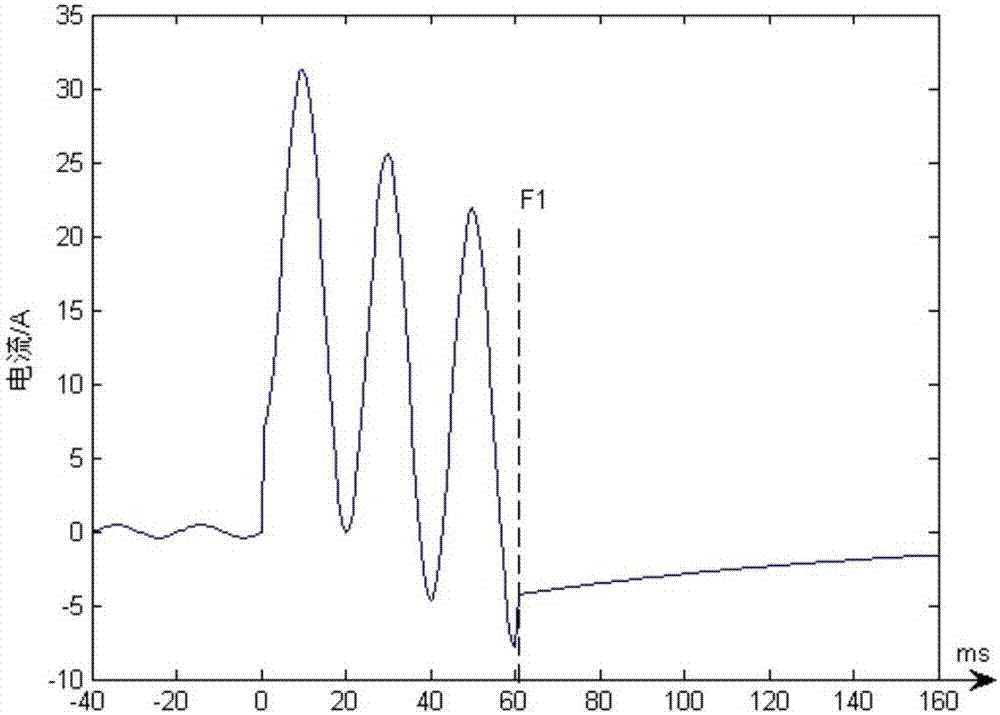
[0047] Such as figure 2 As shown, in the CT trailing current waveform of a certain transmission line fault, the time when the transmission line fault oc...


PUM


Abstract

The invention discloses a rapid detection method of a tail current of a current transformer so that a technical problem of increasing the detection speed of the tail current of the current transformer is solved. The method comprises: acquiring a transmission line parameter; calculating an impedance angle and a decay time constant of a secondary loop; collecting a parameter of a transmission line power voltage before a fault moment; calculating an effective value of a fault current fundamental wave; and comparing the effective value of the fault current fundamental wave with a constant current value of failure protection. Compared with the prior art, the rapid detection method has the following beneficial effects: two-time differential filtering is carried out, the effective value of the fundamental component in the tail current is obtained by means of quarter-cycle absolute value integration, and the effective value is compared with a constant current return value of failure protection to determine whether the effective value is lower than the constant current return value, and the normal operation state is recovered when the fault state is eliminated or the protection action condition is not met, so that the tail current determination time is reduced to be within 10ms, the failure protection action delay is reduced while high reliability is ensured, and the operation risk of the power system is reduced.

Description

technical field [0001] The invention relates to a relay protection method, in particular to a method for detecting tailing current of a current transformer. Background technique [0002] my country's current power grid backbone network is a large AC-DC hybrid power grid. With the massive access of DC power grid systems, the power electronic characteristics of the power grid are becoming more and more obvious. In order to solve the problem of DC blocking caused by the failure of the circuit breaker, the State Grid Corporation of China proposed a solution through the failure of the station domain, requiring the AC grid system to fail. When the circuit breaker fails, all adjacent switches are cut off within 200ms from the moment of the failure. , to prevent multiple commutation failures in the DC grid system. In order to remove the fault within 200ms, it is necessary to compress the action delay of the failure protection. The inherent time of the switching action cannot be com...

Claims


Application Information

Patent Timeline
IPC IPC(8): G01R19/00
CPCG01R19/0092
Inventor 刘宏君俞伟国潘军军王冰清凌昊李炜霞
Owner 长园深瑞继保自动化有限公司
Learn More