Integrated packaged light source

A technology of light source and heat dissipation shell, applied in the direction of semiconductor devices, electrical components, circuits, etc., can solve problems such as general lighting chromaticity, inconvenient electrical connection, easy short circuit between circuit components and aluminum substrates, etc. The effect of running, good chromaticity consistency, good refractive power

Active Publication Date: 2017-11-24
HUNAN YUEGANG MOOKRAY IND CO LTD
View PDF13 Cites 0 Cited by
  • Summary
  • Abstract
  • Description
  • Claims
  • Application Information

AI Technical Summary

Problems solved by technology

The existing LED lamps are inconvenient for electrical connection, and the effects of lighting chromaticity are average, and the direct contact between the circuit components and the aluminum substrate is easy to short circuit

Method used


Image

  • Integrated packaged light source
  • Integrated packaged light source
  • Integrated packaged light source

Examples


Embodiment 1

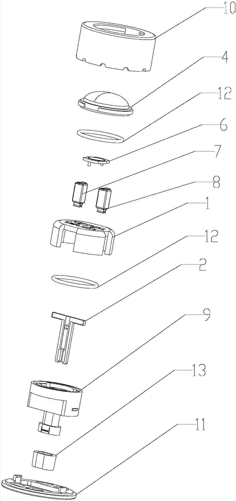
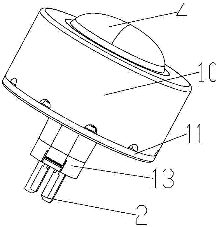
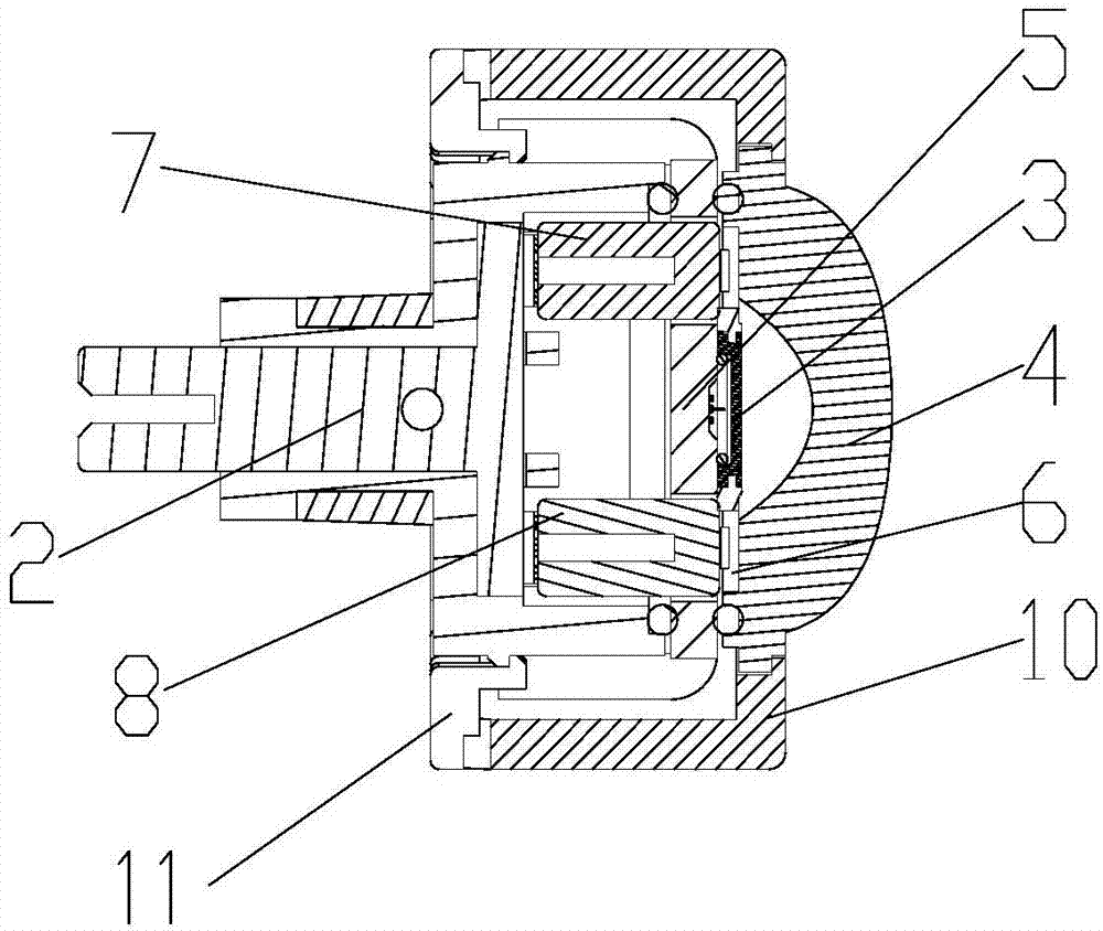
[0022] Such as Figure 1~4 As shown, an integrated packaged light source includes a heat dissipation housing, a heat sink 1, positive and negative plugs 2 and LED chips 3, a lens 4 is provided on the upper end of the heat dissipation housing, and a lens 4 is arranged between the lens 4 and the heat dissipation housing. Cavity; the cavity below the lens 4 is provided with a radiator 1, which is used for heat dissipation and can be set in various shapes. In this embodiment, it is arranged as a ring structure, and the middle part of the radiator 1 is embedded with a LED for packaging. The cup cavity 5 of the chip, the cup cavity 5 is formed by the cup cavity annular dam arranged in the middle of the radiator, the LED chip 3 is attached to the upper end of the cup cavity 5, and the LED chip 3 is covered with a fluorescent sheet 6; The radiator 1 at both ends of the cup chamber 5 is provided with two lead-out holes, and a positive patch terminal 7 and a negative patch terminal 8 ar...

Embodiment 2

[0026] Such as Figure 1~4 As shown, an integrated packaged light source includes a heat dissipation housing, a heat sink 1, positive and negative plugs 2 and LED chips 3, a lens 4 is provided on the upper end of the heat dissipation housing, and a lens 4 is arranged between the lens 4 and the heat dissipation housing. Cavity; the cavity below the lens 4 is provided with a radiator 1, which is used for heat dissipation and can be set in various shapes. In this embodiment, it is arranged as a ring structure, and the middle part of the radiator 1 is embedded with a LED for packaging. The cup cavity 5 of the chip, the cup cavity 5 is formed by the cup cavity annular dam arranged in the middle of the radiator, the LED chip 3 is attached to the upper end of the cup cavity 5, and the LED chip 3 is covered with a fluorescent sheet 6; The radiator 1 at both ends of the cup chamber 5 is provided with two lead-out holes, and a positive patch terminal 7 and a negative patch terminal 8 ar...


PUM


Abstract

The invention discloses an integrated packaged light source, and the light source comprises a heat dissipation housing, heat radiators, a positive plug, a negative plug, and an LED chip. The upper end of the heat dissipation housing is provided with a lens, and there is a cavity between the lens and the heat dissipation housing. The interior of the cavity below the lens is provided with one heat radiator, and the central part of the heat radiator is provided with a cup cavity in an embedded manner. The LED chip is attached to the upper end of the cup cavity, and the LED chip is sleeved by a fluorescent chip. The heat radiators at two ends of the cup cavity are provided with two outlets, and the interiors of the two outlets are respectively attached to a positive paster terminal and a negative paster terminal in a vertical manner. The lower ends of the positive and negative paster terminals are connected with the positive and negative plugs, and the exteriors of the positive and negative plugs are provided with positive and negative plug housings. The heat dissipation housing comprises an upper housing and a bottom cover housing, which are connected through an elastic buckle. The bottom cover housing is disposed at the central part of the positive and negative plug housings in a sleeving manner. The upper ends of the heat radiators are provided with a conductive line which is used for connecting the positive and negative paster terminals and the LED chip. The light source is good in conduction stability, is good in heat dissipation performance, and is good in luminous effect.

Description

technical field [0001] The invention relates to the technical field of LED lamps, in particular to an integrated packaged light source. Background technique [0002] LED light source has the advantages of using low-voltage power supply, low energy consumption, strong applicability, high stability, short response time, no pollution to the environment, multi-color light, etc. With the development of LED lamps, the use of LED lamps is becoming more and more extensive , has increasingly penetrated into people's work and life, and has made great contributions to the beautification of the city and daily use. [0003] In the prior art, an LED lamp is composed of a lamp cap, a lamp body, a circuit assembly, an aluminum substrate, an LED chip and a bulb, the lamp cap is fixed at the lower end of the lamp body, the circuit assembly and the aluminum substrate are installed in the lamp body, and the circuit assembly is electrically connected to the lamp cap , the circuit assembly is el...

Claims


Application Information

Patent Timeline
Patent Type & Authority Applications(China)
IPC IPC(8): H01L33/52H01L33/50H01L33/64H01L33/62
CPCH01L33/50H01L33/52H01L33/62H01L33/64
Inventor 朱衡
Owner HUNAN YUEGANG MOOKRAY IND CO LTD
Why Eureka
Try Eureka