
A method for detecting the initial position of the rotor of a built-in permanent magnet synchronous motor

A permanent magnet synchronous motor and rotor initial position technology, which is applied in the control of generators, motor generator control, electronic commutation motor control, etc., can solve the problems of complex theoretical errors in the initial rotor position process, and achieve a small amount of calculation. Simple, Robust Effects

Active Publication Date: 2019-09-24
NORTHWESTERN POLYTECHNICAL UNIV
View PDF5 Cites 0 Cited by
  • Summary
  • Abstract
  • Description
  • Claims
  • Application Information

AI Technical Summary

Problems solved by technology

[0004] In order to overcome the shortcomings of the existing method of extracting the initial position of the rotor based on high-frequency rotating voltage injection, the process is complex, and there are theoretical errors, the present invention provides a more simple and feasible method for detecting the initial position of the rotor of the built-in permanent magnet synchronous motor

Method used


Image

  • A method for detecting the initial position of the rotor of a built-in permanent magnet synchronous motor
  • A method for detecting the initial position of the rotor of a built-in permanent magnet synchronous motor
  • A method for detecting the initial position of the rotor of a built-in permanent magnet synchronous motor

Examples


Embodiment Construction

[0026] The present invention will be specifically described below in conjunction with the accompanying drawings, and the present invention includes but not limited to the following embodiments.

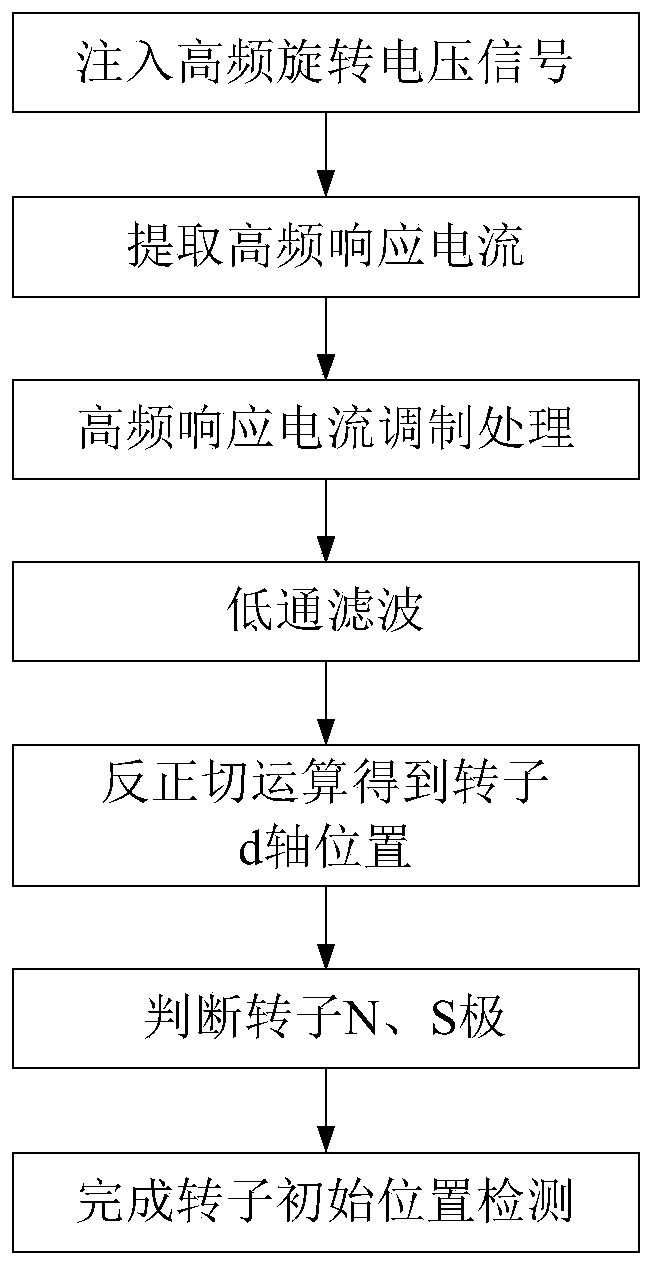
[0027] Such as figure 1 As shown, a method for detecting the initial position of the rotor of a built-in permanent magnet synchronous motor according to the present invention, the implementation process is as follows:

[0028] 1. Extract high-frequency response current: Inject three-phase symmetrical high-frequency voltage signals into the three-phase winding of the permanent magnet synchronous motor stator, and generate corresponding high-frequency response current in the stator. Detect the three-phase response current of the stator, and transform the response current into a two-phase stationary coordinate system by 3 / 2 transformation, and then extract the high-frequency response current through a BPF (band-pass filter, this embodiment adopts a low-order butterworth filter):

[0029...


PUM


Abstract

The invention provides a method of detecting initial position of a built-in permanent magnet synchronous motor rotor. The method of detecting initial position of a built-in permanent magnet synchronous motor rotor includes the steps: taking a high frequency response current signal as a modulation signal to perform modulation processing on the high frequency response current, and then performing low pass filtering; through simple operation, obtaining the positional information of d shaft of the motor rotor; and utilizing a magnetic circuit saturation principle to distinguish N and S poles to complete detection of the initial position of the rotor. The method of detecting initial position of a built-in permanent magnet synchronous motor rotor saves a series of steps of a traditional high frequency injection method of detecting the position of a rotor, including extracting rotor negative phase-sequence component or performing linear approximation and curve fitting after extracting high frequency response current, and has the advantages of being easy to implement, being low in computational complexity, eliminating the influence of motor parameters during the computation process, and being high in robustness.

Description

technical field [0001] The invention belongs to the technical field of motor control, and in particular relates to a method for detecting the initial position of a built-in permanent magnet synchronous motor rotor based on rotating high-frequency voltage injection. Background technique [0002] At present, the research on the position sensorless control method of permanent magnet synchronous motor has a long history. The current detection method of the initial position of the permanent magnet synchronous motor rotor based on the injection of rotating high-frequency voltage mostly adopts the method of injecting the rotating high-frequency voltage signal into the stator winding, and the winding responds to the current The high-frequency response current is extracted by band-pass filtering. The high-frequency response current contains positive-sequence current components and negative-sequence current components. The negative-sequence current component contains rotor position inf...

Claims


Application Information

Patent Timeline
Patent Type & Authority Patents(China)
IPC IPC(8): H02P21/32H02P21/18
CPCH02P21/18H02P21/32
Inventor 刘景林陈双双于昊正席海杰张二阳
Owner NORTHWESTERN POLYTECHNICAL UNIV
Learn More