Electronic equipment heat conduction, vibration reduction plug -in lock component

An electronic device and plug-in technology, which is applied in the direction of support structure installation, clamping/extracting device, etc., can solve the problems of easy deflection of the bar slider, large shaking of the bar slider, and jamming, etc., so as to avoid screw teeth Heavy wear, good heat dissipation and vibration damping capabilities, reducing the effect of moving parts

Active Publication Date: 2019-06-28
10TH RES INST OF CETC
View PDF7 Cites 2 Cited by
  • Summary
  • Abstract
  • Description
  • Claims
  • Application Information

AI Technical Summary

Problems solved by technology

[0005] In actual use, limited by the U-shaped groove structure and external dimensions of the locking device, the sliding contact area of ​​the U-shaped inclined end surface of each wedge block is small (such as Figure 10 The middle and rear locking slope 10), under the action of the extrusion force of the locking stroke, the wedge-shaped blocks are prone to slipping and jamming; due to size restrictions, M2.5 or M2 nuts must be selected, and the thread meshing with the screw rod is less, After many times of use, the screw teeth are seriously worn, and the threads cannot be meshed normally; in order to ensure that the bar slider can slide up and down normally, there must be a large gap between the bar slider and the screw, which brings the bar slider on the screw. The defect of large shaking makes the bar slider deflect easily and get stuck in the slot when locking; in addition, the wedge block is a hollow U-shaped cross-section structure, and the heat conduction between the wedge blocks and between the wedge block and the central rod The contact area is small, which is not conducive to the conduction and heat dissipation of electronic modules or printed circuit boards to the chassis
The existing wedge-shaped locking devices are all rigid tight fits, lacking the design of vibration energy dissipation mechanism, and cannot block or reduce the transmission of vibration energy between the chassis and electronic modules or printed circuit boards

Method used


Image

  • Electronic equipment heat conduction, vibration reduction plug -in lock component
  • Electronic equipment heat conduction, vibration reduction plug -in lock component
  • Electronic equipment heat conduction, vibration reduction plug -in lock component

Examples


Embodiment 1

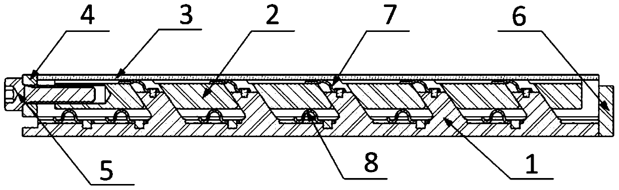
[0027] see figure 1 , figure 2 with image 3, a high thermal conductivity self-vibration-damping locking assembly for electronic modules or equipment inserts, which has a bar-shaped slider 2 mounted on a bar-shaped base 1 and can slide up and down, and a housing installed on the bar-shaped slider 2 Body 3, screw rod 5 and positioning block 4. A plurality of slanted columns or slanted teeth are designed on the strip base 1 along the longitudinal direction, and the same number of slanted holes or slanted slots are provided at the corresponding positions on the bar-shaped slider 2. Install the bar-shaped slider 2 on the bar-shaped base 1, the bar-shaped base 1 and the bar-shaped slider 2 are integral structures; the outer shell 3 is set on the bar-shaped slider 2, and the fixed limit block 4 is installed on the outer shell 3 left end, the screw rod 5 passes through the limit block 4 and is threadedly connected with the bar slider 2, and the limit block 6 is installed on the ...

Embodiment 2

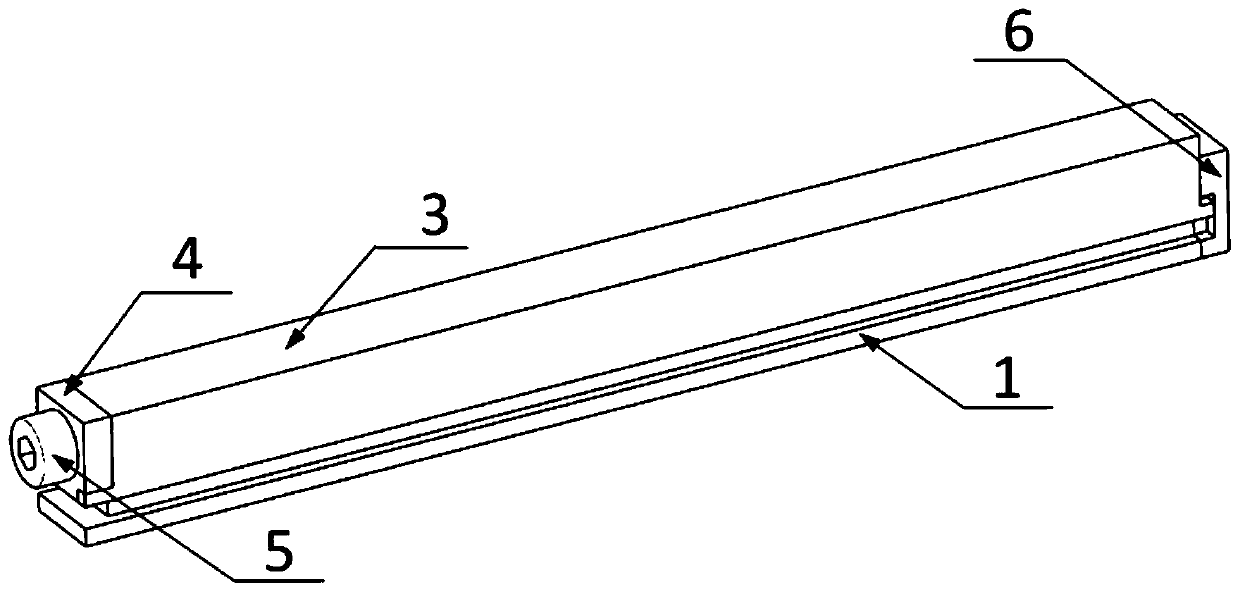
[0030] refer to Figure 4 with Figure 5 . The difference between this embodiment and Embodiment 1 is that the outer casing 3 and the bow-shaped shrapnel 7 are removed, and the left end of the bar-shaped base 1 is designed with a limit guide groove, and the fixed limit block 4 is installed in the limit guide groove; The oblique through hole is changed into an oblique blind hole, and its right end face is designed with a limit post to cooperate with the limit block 6. Other compositional structures and figure 1 The described embodiment is the same.

Embodiment 3

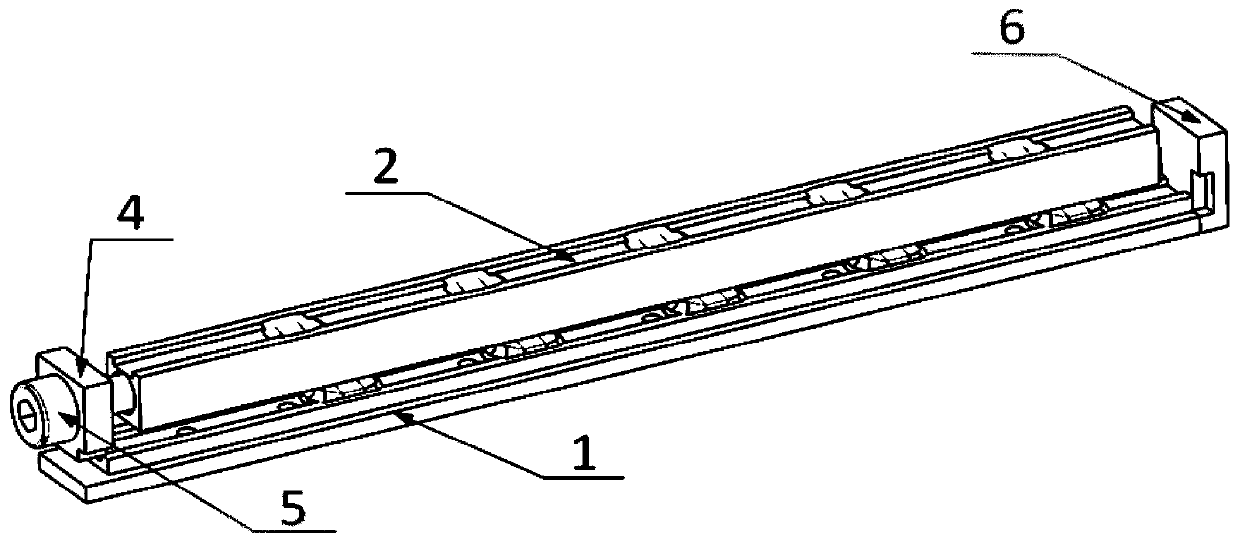
[0032] refer to Image 6 with Figure 7 . The difference between this embodiment and Embodiment 1 is that the bow-shaped shrapnel 7 is removed, the slanted column on the upper part of the strip base 1 is changed to helical teeth, and the slanted through hole of the bar slider 2 is changed to a chute. Cooperate, the bar-shaped slider 2 is inserted on the bar-shaped base 1, and at least two Ω-shaped shrapnel 8 are riveted on the plane below the bar-shaped slider 2 . Other compositional structures and figure 1 The described embodiment is the same.


PUM


Abstract

The invention discloses a thermal conductive damping plug-in locking assembly for electronic equipment, and aims to provide a fast locking assembly controllable in force transfer and reliable in locking. The locking assembly comprises a bar sliding block (2) which is mounted on a bar base (1) and can slide, a plurality of oblique cylinders or oblique teeth arranged longitudinally are made on the bar base (1), the same number of oblique holes or oblique slots are formed in the bar sliding block (2), special-shaped elastic elements are mounted between the bottoms of the oblique holes or oblique slots of the bar sliding block and the tops of the oblique cylinders or oblique teeth of the bar base, and the oblique cylinders or oblique teeth on the bar base are inserted into the oblique holes or oblique slots of the bar sliding block; and under the coordination of a fixed limiting block (4) and a limiting block (6) mounted at two ends of the bar base, the bar sliding block is pulled or pushed via a screw (5) connected to the fixed limiting block and the bar sliding block, to drive an outer shell (3) to slide up and down on the bar base. The locking assembly is applicable to fast locking and fixation of an electronic module or a PCBA (Printed Circuit Board Assembly) installed in a case slot of the electronic equipment.

Description

technical field [0001] The invention relates to a fast fixing / dismounting mechanical locking assembly with heat dissipation and vibration reduction capability for inserting electronic modules and printed circuit board assemblies (hereinafter referred to as PCBA) in electronic equipment. Background technique [0002] In the design of modern electronic equipment, in order to improve the efficiency of on-site repair and maintenance, a large number of standard electronic modules or standard PCBA plug-ins are used, that is, each module or PCBA has independent functions, and its appearance and interface size are uniform. During maintenance, directly take out the faulty module or PCBA from the equipment case, replace the backup module or PCBA of the same model, the system can resume working immediately, and the replaced faulty module or PCBA will be sent to the designated place for repair and backup. In the current on-site use and maintenance of electronic equipment, there must be ...

Claims


Application Information

Patent Timeline
Patent Type & Authority Patents(China)
IPC IPC(8): H05K7/14
CPCH05K7/1405H05K7/1407
Inventor 何敏
Owner 10TH RES INST OF CETC
Why Eureka
Try Eureka