Machining method for nozzle steam channel

A processing method and steam channel technology, applied in the field of steam turbines, can solve the problems affecting machining efficiency, large deviation of nozzle steam channel pitch, reducing processing efficiency, etc., so as to ensure processing efficiency and processing quality, avoid large pitch deviation, Ensure the effect of processing quality

Inactive Publication Date: 2017-11-28
HARBIN TURBINE
View PDF6 Cites 2 Cited by
  • Summary
  • Abstract
  • Description
  • Claims
  • Application Information

AI Technical Summary

Problems solved by technology

[0007] The purpose of the present invention is to solve the problem that the existing nozzle steam channel adopts the electric discharge machining method. There is a hardened layer on the surface after processing, which affects the machining efficiency. The pitch deviation of the electric discharge machining nozzle steam channel is large, resulting in uneven machining allowance. , reduce processing efficiency, affect product quality, and there is a problem that the rightmost air passage cannot be processed due to the interference between the EDM electrode and the workpiece, and then a processing method for the nozzle air passage is provided

Method used


Image

  • Machining method for nozzle steam channel
  • Machining method for nozzle steam channel
  • Machining method for nozzle steam channel

Examples


specific Embodiment approach 1

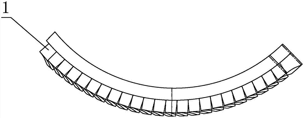
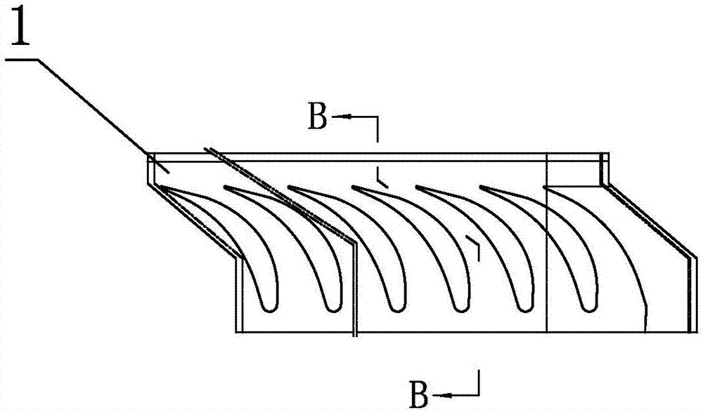
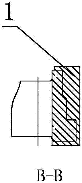
[0041] Specific implementation mode one: combine Figure 1 to Figure 9 Describe this embodiment, a method for processing a nozzle air passage in this embodiment, the method includes the following steps,

[0042] Step 1. Roughly machining the inlet and outlet sides of steam channel 1 of the nozzle:

[0043] According to the steam channel width, select the first milling cutter with a diameter of 10mm-14mm to roughly machine the inlet and outlet sides of the nozzle steam channel 1, the speed is 2000r / min-2500r / min, the cutting depth is 1mm, and the cutting amount per blade is 0.01mm -0.02mm;

[0044] Step 2. Rough machining the middle part of the nozzle steam channel 1:

[0045] According to the width of the steam channel, the second milling cutter with a diameter of 6mm×R2mm-10mm×R2mm is used to roughly machine the middle part of the nozzle steam channel 1, the speed is 2000r / min-2500r / min, the cutting depth is 1mm, and the cutting amount per blade is 0.01 mm-0.02mm;

[0046...

specific Embodiment approach 2

[0050] Specific implementation mode two: combination Figure 7To illustrate this embodiment, the rotation speed of the first milling cutter in Step 1 of this embodiment is 2250r / min, the cutting depth is 1mm, and the cutting amount per blade is 0.01mm. With this arrangement, the first milling cutter is used to roughly machine the inlet and outlet sides of the nozzle steam channel 1, which avoids the existence of a hardened layer on the rear surface of the traditional EDM nozzle steam channel, makes the margin after rough machining more uniform, and effectively improves the The processing efficiency is not limited by the tool, and there will be no interference, which ensures the processing quality. Other compositions and connections are the same as in the first embodiment.

specific Embodiment approach 3

[0051] Specific implementation mode three: combination Figure 8 To illustrate this embodiment, the rotation speed of the second milling cutter in step 2 of this embodiment is 2500r / min, the cutting depth is 1mm, and the cutting amount per blade is 0.02mm. In this way, the middle part of the nozzle steam channel 1 is roughly machined with the second milling cutter, which avoids the hardened layer on the rear surface of the traditional EDM nozzle steam channel, makes the margin after rough machining more uniform, and effectively improves the processing efficiency. It is not limited by the tool, and there will be no interference, which ensures the processing quality. Other compositions and connections are the same as those in Embodiment 1 or Embodiment 2.


PUM


Abstract

The invention relates to a method for processing nozzle steam channels, which relates to the field of steam turbines. The invention solves the problem that the existing nozzle steam channel adopts the electric discharge machining method, and there is a hardened layer on the surface after processing, which affects the machining efficiency. Efficiency affects product quality, and there is a problem that the rightmost steam channel cannot be processed due to the interference between the EDM electrode and the workpiece. The method of the present invention comprises the following steps: 1. Rough machining the inlet and outlet sides of the nozzle steam passage, the rotating speed is 2000r / min, the cutting depth is 1mm, and the cutting amount per blade is 0.01mm; 2. Rough machining the nozzle steam passage In the middle part, the speed is 2500r / min, the cutting depth is 1mm, and the cutting amount per blade is 0.02mm; 3. The leaf shape of the semi-finishing nozzle air passage, the speed is 3200r / min, the cutting depth is 1mm, and the cutting amount per blade is 0.03mm; 4. Finishing the leaf shape of the nozzle steam channel, the speed is 3000r / min, the cutting depth is 1mm, and the cutting amount per blade is 0.02mm. The invention is used for the processing of the nozzle steam channel.

Description

technical field [0001] The invention relates to the field of steam turbines, in particular to a method for processing nozzle steam passages. Background technique [0002] Turbine nozzles are also called stationary vanes. It is a channel with a special and constantly changing cross-sectional shape. After the steam enters the nozzle, it expands and consumes the pressure energy of the steam, that is, the heat energy of the steam. The pressure and temperature of the steam drop, but the flow rate of the steam increases, and a high-speed airflow is obtained. The role of the nozzle is to convert the thermal energy of the steam into kinetic energy. The existing machining method of the nozzle steam channel is to use EDM to rough-machine the leaf shape first, leave a machining allowance of 0.8mm, and then use machining to finish the quasi-leaf shape, and finally complete the machining of the nozzle steam channel. Such as Figure 10 As shown, the existing nozzle steam channel proces...

Claims


Application Information

Patent Timeline
Patent Type & Authority Applications(China)
IPC IPC(8): B23P15/00
CPCB23P15/00
Inventor 陈钊杨庆仁林彬彬吕思佳庄乾才崔会彬季东军
Owner HARBIN TURBINE
Why Eureka
Try Eureka