Radio frequency receiver for magnetic resonance imaging system and magnetic resonance imaging system

A radio frequency receiver, magnetic resonance imaging technology, applied in magnetic resonance measurement, measurement of magnetic variables, measurement devices, etc., can solve the problems of high insertion loss, pass bandwidth, limited resonator, etc., and achieve both narrowband and low insertion loss. , the effect of high out-of-band rejection

Inactive Publication Date: 2017-11-28
SHANGHAI UNITED IMAGING HEALTHCARE
View PDF4 Cites 1 Cited by
  • Summary
  • Abstract
  • Description
  • Claims
  • Application Information

AI Technical Summary

Problems solved by technology

However, the out-of-band rejection of the SAW filter cannot be very high, and the band-side rejection cannot be made very steep, so that the interference signal of the adjacent channel can easily enter the back end of the receiver, reducing the signal-to-noise ratio of the signal, and the present Some SAW filters, for example, have sideband suppression of only about 40-50dB, and the insertion loss in the passband is as high as 2dB, and the passband is wide, which cannot take into account narrowband, high out-of-band rejection and low insertion loss; ordinary materials are used The resonator built by the microstrip line or stripline constitutes a bandpass filter. On the one hand, it is limited by the Q value of the resonator itself, and on the other hand, it is limited by the size of the resonator built by ordinary materials in the low frequency band, making it impossible to balance High out-of-band rejection and low insertion loss

Method used


Image

  • Radio frequency receiver for magnetic resonance imaging system and magnetic resonance imaging system
  • Radio frequency receiver for magnetic resonance imaging system and magnetic resonance imaging system

Examples


Embodiment Construction

[0019] In order to make the object, technical solution and advantages of the present invention clearer, the present invention will be further described in detail below in conjunction with the accompanying drawings and embodiments. It should be understood that the specific embodiments described here are only used to explain the present invention, not to limit the present invention.

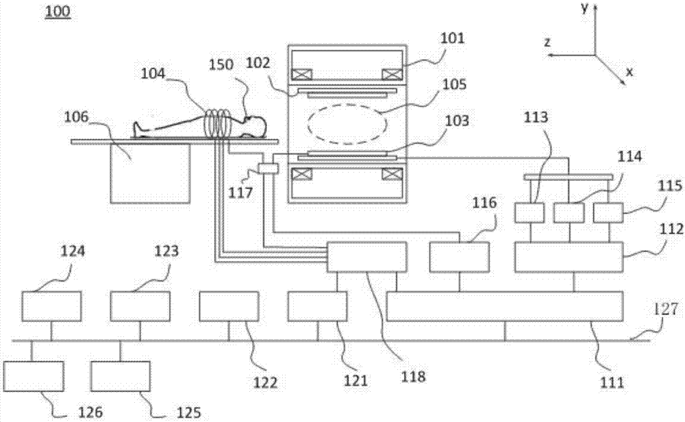
[0020] figure 1 is a structural schematic diagram of a magnetic resonance system in some embodiments of the present invention, such as figure 1 As shown, the magnetic resonance system 100 generally includes a magnetic resonance frame, and there is a main magnet 101 in the frame. The main magnet 101 may be composed of a superconducting coil to generate a main magnetic field. In some cases, a normal conductor, a permanent magnet. The main magnet 101 can be used to generate a main magnetic field strength of 0.2 Tesla, 0.5 Tesla, 1.0 Tesla, 1.5 Tesla, 3.0 Tesla or higher. During magnetic resonance i...


PUM


Abstract

The present invention relates to a radio frequency receiver for a magnetic resonance imaging system. The radio frequency receiver comprises a low temperature maintaining system and a superconducting filter accommodated in the low temperature maintaining system; and the superconducting filter is connected with a radio frequency coil and is used for receiving radio frequency signals outputted by the radio frequency coil and filtering the radio frequency signals. According to the radio frequency receiver and the magnetic resonance imaging system of the present invention, the superconducting filter is arranged in the low temperature maintaining system; the superconducting filter is designed based on a superconducting principle, so that the out-of-band suppression of the superconducting filter can be very high, and the sideband suppression of the superconducting filter can also be very steep, and therefore, interference signals near channels can be easily filtered out and cannot pass through the superconducting filter; and after the radio frequency receiver of the present invention is provided with the superconducting filter, the sideband suppression of the radio frequency receiver can achieve about 80 to 90dB, the in-passband insertion loss of the radio frequency receiver can be as low as 0.5dB, the passband of the radio frequency receiver is narrow, and therefore, the narrowband, high out-of-band rejection and low insertion loss of the radio frequency receiver can be well balanced. The invention also relates to a magnetic resonance imaging system.

Description

technical field [0001] The invention relates to the field of medical equipment, in particular to a radio frequency receiver for a magnetic resonance imaging system and the magnetic resonance imaging system. Background technique [0002] The magnetic resonance imaging system is a device that uses the principle of nuclear magnetic resonance to generate medical images. The magnetic resonance imaging system usually has a main magnet, a gradient system and a radio frequency system. The main magnet is used to generate the main magnetic field. The main magnet can be used to generate 0.2 Tesla, 0.5 T Tesla, 1.0 Tesla, 1.5 Tesla, 3.0 Tesla or higher main magnetic field strength; the gradient system is used to generate a gradient field added to the main magnetic field for spatial positioning, so as to provide imaging objects in vivo The three-dimensional coordinate information of the proton magnetic resonance signal; the radio frequency system is used to transmit radio frequency pulse...

Claims


Application Information

Patent Timeline
IPC IPC(8): G01R33/36
CPCG01R33/3621
Inventor 侯方焰
Owner SHANGHAI UNITED IMAGING HEALTHCARE
Why Eureka
Try Eureka