
Design of efficient circular polarization beam splitter

A circularly polarized wave and circularly polarized technology, applied in the microwave field, can solve the problems of limited polarization separation angle, complex structure of polarization separator, and high price

Active Publication Date: 2017-11-28
AIR FORCE UNIV PLA
View PDF2 Cites 13 Cited by
  • Summary
  • Abstract
  • Description
  • Claims
  • Application Information

AI Technical Summary

Problems solved by technology

[0004] The above polarization separators have the following defects: the polarization separator designed with birefringent crystals must rely on natural birefringent crystals to realize, and is extremely sensitive to the incident angle of electromagnetic waves; the polarization separator designed with photonic crystals has a complex structure, The electromagnetic energy loss is large, and the polarization separation angle is limited at the same time; the polarization separator designed with semiconductor devices and integrated circuits introduces active components, which are expensive, and the active components destroy the polarization independence of the two dimensions. The degree of polarization separation is reduced; the polarization splitter designed with anisotropic metamaterials and two-dimensional graded index metamaterials is mainly based on optical path difference to achieve beam control, the device is relatively bulky, and the degree of polarization separation is not high. high
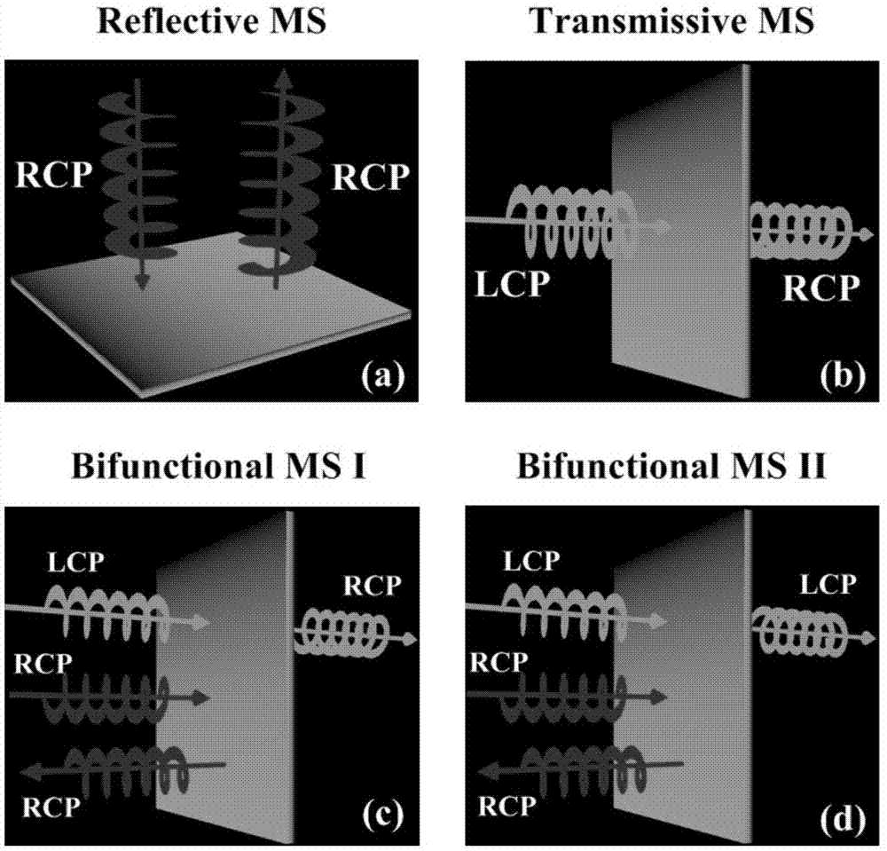
Moreover, the polarization separators reported above all work in the linear polarization state, and there is no report on the polarization separation of circularly polarized waves.

Method used


Image

  • Design of efficient circular polarization beam splitter
  • Design of efficient circular polarization beam splitter
  • Design of efficient circular polarization beam splitter

Examples


Embodiment Construction

[0017] The technical solution of the present invention will be described in further detail below in conjunction with the accompanying drawings and specific embodiments. It should be understood that the specific embodiments described here are only used to explain related inventions, not to limit the invention. It should also be noted that, for the convenience of description, only the parts related to the related invention are shown in the drawings.

[0018]It should be noted that, in the case of no conflict, the embodiments in the present application and the features in the embodiments can be combined with each other. The present application will be described in detail below with reference to the accompanying drawings and embodiments.

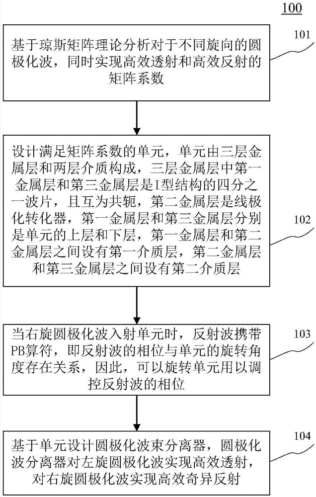
[0019] refer to figure 1 , shows a flowchart 100 of one embodiment of a high-efficiency circular polarization beam splitter according to the present application. The design of a high-efficiency circular polarization beam splitter includes the...


PUM


Abstract

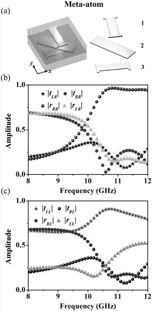
The invention discloses an efficient circular polarization beam splitter. One specific implementation manner of the circular polarization beam splitter comprises steps of based on Jones matrix theory analysis, realizing matrix coefficients of efficient transmission and efficient reflection of circular polarization waves of different rotation directions simultaneously; designing a unit meeting the matrix coefficients, wherein the unit comprises three metal layers and two layers of medium, the first metal layer and the third metal layer are quarter-wave plates of an I structure and are mutually conjugate, and the second metal layer is a linear polarization converter; when a right-hand circular polarization wave enters the unit, and a reflected wave carries a Pancharatnam-Berry (PB) operator, rotating the unit to control a phase of the reflected wave; and designing, based on the unit, the circular polarization beam splitter so as to realize efficient transmission of a left-hand circular polarization wave and efficient singular reflection of the right-hand circular polarization wave. The circular polarization beam splitter has high working efficiency, over 90%, for both the left-hand circular polarization wave and the right-hand circular polarization wave.

Description

technical field [0001] The invention belongs to the field of microwave technology, in particular to a design of a circular polarization beam splitter based on a PB metasurface. Background technique [0002] Electromagnetic metasurfaces have unique advantages in controlling the amplitude, phase, and polarization characteristics of electromagnetic waves, and have been widely used in the design of electromagnetic devices and in improving the performance of electromagnetic devices. As an important device for electromagnetic wave polarization control, polarization separator has important application prospects in the fields of communication engineering, radar system and wave front control system. [0003] There are five main implementations of polarization separators. Traditional technology is mainly realized by using natural birefringent crystals. Based on the birefringent properties of crystals, different electromagnetic responses can be formed for electromagnetic waves with di...

Claims


Application Information

Patent Timeline
Patent Type & Authority Applications(China)
IPC IPC(8): H01Q15/24
CPCH01Q15/24
Inventor 梁建刚蔡通王光明冉屿舟侯海生
Owner AIR FORCE UNIV PLA
Learn More