Power converter
A power conversion device and power conversion technology, applied in the direction of output power conversion devices, electrical components, and adjustment of electrical variables, can solve the problem of low noise reduction effect and achieve the effect of reducing common mode noise
- Summary
- Abstract
- Description
- Claims
- Application Information
AI Technical Summary
Problems solved by technology
Method used
Image
Examples
Embodiment 1
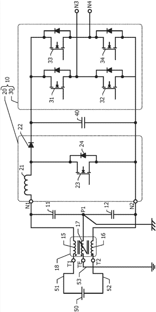
[0039] refer to figure 1 and FIG. 2 , the power conversion device according to the first embodiment will be described.
[0040] figure 1 An equivalent circuit diagram of the power conversion device according to the first embodiment is shown. The power conversion device according to Embodiment 1 includes external terminals T1 , T2 , a ground terminal (Earth Terminal) TE, a common mode choke coil 18 , and a power conversion circuit 10 . The power conversion circuit 10 includes a step-up converter 20 and an inverter 30 , and converts input DC power into AC power for output.
[0041] The external terminals T1 and T2 are respectively connected to the positive pole and the negative pole of the DC power supply 50 through the positive line 51 and the negative line 52 . The ground terminal TE is connected (grounded) to the earth through the ground wire 53 and is fixed at the same potential as the earth surface. The DC power supply 50 uses, for example, a solar panel, a fuel cell, o...
Embodiment 2
[0060] Next, refer to Figure 4 ~ Figure 6A , Figure 6B The accompanying drawings describe a power conversion device based on Embodiment 2. Hereinafter, differences from Embodiment 1 will be described, and descriptions of common configurations will be omitted.
[0061] Figure 4 An equivalent circuit diagram of the power conversion device according to the second embodiment is shown. In Embodiment 1, inductors 15, 16, 17 form a three-phase common mode choke coil 18 ( figure 1 ). exist Figure 4 In the shown embodiment 2, the inductors 15, 16, and 17 are constituted by independent coils, and there is no inductive coupling. The three inductors 15, 16, and 17 have the same electromagnetic characteristics.
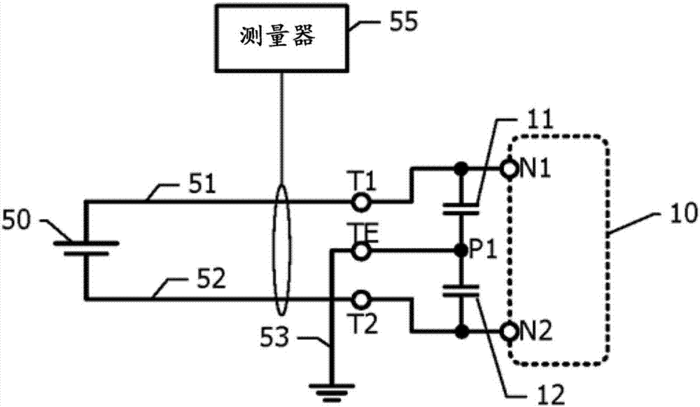
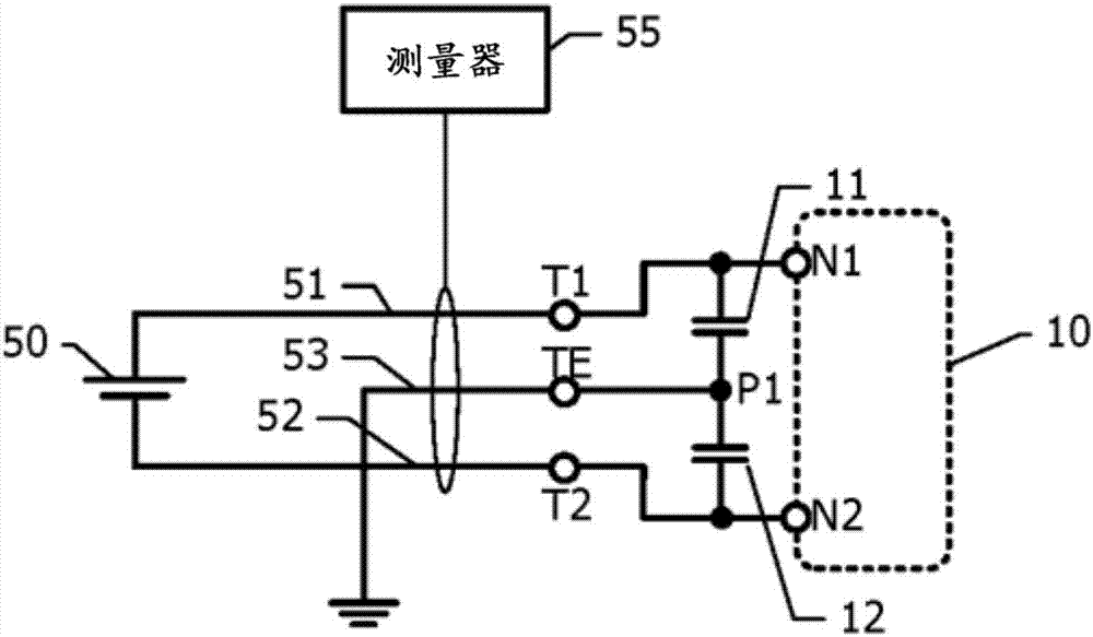
[0062] refer to Figure 5A as well as Figure 5B , the respective electrical characteristics of the inductors 15, 16, and 17 will be described. Consists of an inductor 15 Figure 5B The two-terminal pair circuit is shown, and the transfer characteristic S21 is measu...
Embodiment 3
[0071] Next, refer to Figure 7 , the power conversion device based on Embodiment 3 will be described. Hereinafter, differences from Embodiment 1 will be described, and descriptions of common configurations will be omitted. In the first embodiment, the three-phase common mode choke coil 18 is inserted on the input side of the power conversion circuit 10 , but in the third embodiment, the three-phase common mode choke coil 18 is inserted on the output side of the power conversion circuit 10 . In addition, three-phase common mode choke coils 18 may be inserted on both the input side and the output side.
[0072] Figure 7 An equivalent circuit diagram of the power conversion device according to the third embodiment is shown. The power system 70 is connected to external terminals T3 and T4 on the output side of the power conversion device. The ground terminal TE is grounded.
[0073] Two inductors 62 and capacitors 61 are arranged between the nodes N3 and N4 on the output s...
PUM
 Abstract
Description
Claims
Application Information
 - R&D
- Intellectual Property
- Life Sciences
- Materials
- Tech Scout
- Unparalleled Data Quality
- Higher Quality Content
- 60% Fewer Hallucinations
Browse by: Latest US Patents, China's latest patents, Technical Efficacy Thesaurus, Application Domain, Technology Topic, Popular Technical Reports.
© 2025 PatSnap. All rights reserved.Legal|Privacy policy|Modern Slavery Act Transparency Statement|Sitemap|About US| Contact US: help@patsnap.com


