Synchronous rectification switching-converter

A switching converter and synchronous rectification technology, which is applied in the direction of DC power input conversion to DC power output, conversion equipment with intermediate conversion to AC, output power conversion device, etc., which can solve the problems of FET element Q4 damage and so on

Active Publication Date: 2017-11-28
SANSHA ELECTRIC MFG
View PDF5 Cites 0 Cited by
  • Summary
  • Abstract
  • Description
  • Claims
  • Application Information

AI Technical Summary

Problems solved by technology

At this time, when the FET element Q4 is turned off at the timing when the reactor current is negative, that is, the timing at which the current flows from the reactor L→FET element Q4→capacitor C→reactor L, the energy stored in the reactor L is The two ends of the element Q4 generate excessive surge voltage (surge voltage) Vs, sometimes reaching the destruction of the FET element Q4

Method used


Image

  • Synchronous rectification switching-converter
  • Synchronous rectification switching-converter
  • Synchronous rectification switching-converter

Examples


Embodiment Construction

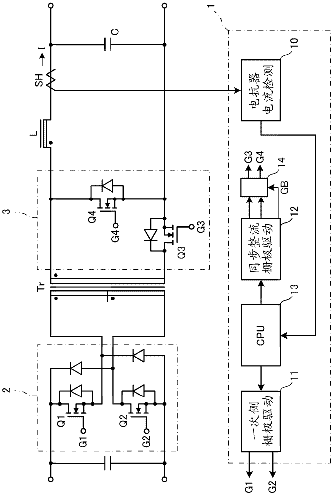
[0035] image 3 It is a circuit diagram of a synchronous rectification switching converter as an embodiment of the present invention.

[0036] A two-transistor forward switching circuit 2 including FET elements Q1 and Q2 is connected to the primary side of the transformer Tr, and a synchronous rectification circuit 3 including two FET elements Q3 and Q4 is connected to the secondary side. The first FET element Q3 of the synchronous rectification circuit 3 is a rectification-side FET element, and the second FET element Q4 is a return-side FET element. The first and second FET elements Q3 and Q4 are turned on and off instead of conventional diodes, thereby supplying rectified electric power to the load side. A smoothing circuit composed of a reactor L and a capacitor C is connected to the load side of these FET elements Q3 and Q4, and a current detection sensor SH for the reactor current is connected in series with the reactor L, and the output of the current detection sensor S...


PUM


Abstract

A synchronous rectification type switching-converter is provided with: a synchronous rectifier circuit connected to the secondary side of a transformer; and a control circuit for on / off controlling a primary side switching circuit and the synchronous rectifier circuit at each sampling timing. The control circuit is provided with: a gate blocking means for, when a detection value detected by a reactor current detection sensor and a predetermined threshold value are compared with each other and the detection value becomes less than or equal to the threshold vale, outputting a gate blocking signal for stopping the operation of a synchronous rectification element; and a correction means for, when the gate blocking means compares the detection value currently sampled by the detection sensor with the predetermined threshold value upon detecting, on the basis of the detection value detected by the detection sensor, that the decrease of the reactor current is a certain level or more, correcting either the detection value or the threshold value with reference to the history of the detection value detected by the detection sensor.

Description

technical field [0001] The present invention relates to a synchronous rectification switching converter using FETs as rectification elements on the secondary side of a transformer, and more particularly to a control circuit thereof. Background technique [0002] Among switching converters in which a switching circuit is connected to a primary side of a transformer and a rectification circuit is connected to a secondary side, there is a synchronous rectification circuit type switching converter in which FETs are used as a rectification circuit. In this synchronous rectification switching converter, the on-resistance of the FET is lower than that of the diode, so there is an advantage of reducing heat loss and improving efficiency. [0003] figure 1 is a schematic circuit diagram of the synchronous rectification switching converter. [0004] A switching circuit (such as a 2-transistor forward switching circuit) including FET elements Q1 and Q2 is connected to the primary sid...

Claims


Application Information

Patent Timeline
IPC IPC(8): H02M3/28
CPCH02M3/28H02H7/1213H02M3/335H02M1/0009
Inventor 川端龙哉小田悠介
Owner SANSHA ELECTRIC MFG
Why Eureka
Try Eureka