Cylinder sleeve cutting equipment capable of achieving scrap suction conveniently

A technology for cutting equipment and cylinder liners, which is applied in the direction of shearing machine equipment, metal processing equipment, shearing devices, etc., and can solve the problems that the degree of automation of cutting efficiency needs to be improved, the cutting accuracy and feeding efficiency are affected, and the cutting effect cannot be guaranteed. , to achieve the effect of stable feeding, uniform and stable length, and convenient cleaning

Inactive Publication Date: 2017-12-01
ZYNP GRP ANHUI CO LTD
View PDF7 Cites 7 Cited by
  • Summary
  • Abstract
  • Description
  • Claims
  • Application Information

AI Technical Summary

Problems solved by technology

The manual cutting method is labor-intensive, the cutting efficiency is low, and the cutting effect cannot be guaranteed
Although mechanical cutting can achieve high-precision cutting of the cylinder liner, a large amount of waste chips will be generated during the cutting process. As time goes by, the waste chips will accumulate more and more, and the waste chips will be mixed between the cutting wheel and the cylinder liner. It affects cutting accuracy and feeding efficiency. In addition, manual loading and unloading are required during the processing process, which is labor-intensive, and cutting efficiency and automation need to be improved.

Method used


Image

  • Cylinder sleeve cutting equipment capable of achieving scrap suction conveniently
  • Cylinder sleeve cutting equipment capable of achieving scrap suction conveniently
  • Cylinder sleeve cutting equipment capable of achieving scrap suction conveniently

Examples


Embodiment Construction

[0036] The content of the present invention will be described below in conjunction with specific embodiments.

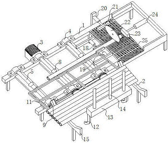
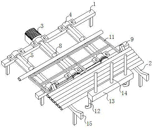
[0037] Such as figure 1 with Figure 7 As shown, the present invention proposes a cylinder liner cutting device for facilitating chip suction, and a cylinder liner cutting device for facilitating chip suction, including a cutting device and a chip suction device. The cutting device is used to cut the cylinder liner. The dust suction device is used to suck away the waste generated in the cutting process.

[0038] Reference figure 1 , The cutting device includes a cutting table 25, the cutting table 25 is knitted by plain weave steel wire, the cutting table 25 is provided with a baffle plate 23 on one side, the baffle plate 23 is located in the feed stroke of the cylinder liner Above, the baffle plate 23 is drivingly connected to the movable end of the third hydraulic cylinder 24 and is driven by the third hydraulic cylinder 24 to move horizontally. The direction of moveme...


PUM


Abstract

The invention discloses a cylinder liner cutting device that is convenient for chip suction, comprising a cutting table, the cutting table is made of plain warp and weft weaving of steel wires, a material blocking plate is arranged on one side of the cutting table, and the material blocking plate is located on the feeding stroke of the cylinder liner , the baffle plate is driven and connected to the movable end of the third hydraulic cylinder, and is driven by the third hydraulic cylinder to move horizontally. The movement direction of the baffle plate is parallel to the feeding direction of the cylinder liner; the other side of the cutting table is also equipped with a pusher The material plate, the pushing plate is driven and connected with the movable end of the seventh hydraulic cylinder, and is driven by the seventh hydraulic cylinder to move horizontally, and the moving direction of the pushing plate is perpendicular to the feeding direction of the cylinder liner; the chip suction device includes a chip suction tube , chip box and fan, the inlet of the chip suction pipe is located under the cutting table, the outlet of the chip suction pipe is connected to the chip box, and the fan is located on the side of the chip box. The cylinder liner cutting equipment which is convenient for chip suction disclosed by the invention can remove the waste chips generated in the cutting process, and has low labor intensity, short processing time and high processing efficiency.

Description

Technical field [0001] The invention relates to the field of cylinder liner production, in particular to a cylinder liner cutting device which is convenient for sucking debris. Background technique [0002] A car engine is a machine that can convert other forms of energy into mechanical energy. It is the heart of the car and affects its power, economy and environmental protection. As one of the main accessories of the engine, the cylinder liner is an A-level key component of the engine. Its performance directly affects the engine's power, reliability, economy, emission, noise and other technical requirements. [0003] In the process of cylinder liner production, it is necessary to cut the cast cylinder liner to a fixed length. The traditional cutting method is nothing more than manual cutting and mechanical cutting. The manual cutting method is labor intensive, the cutting efficiency is low, and the cutting effect is not guaranteed. Although mechanical cutting can achieve high-pr...

Claims


Application Information

Patent Timeline
Patent Type & Authority Applications(China)
IPC IPC(8): B23D19/00B23D33/00B23Q11/00
CPCB23D19/00B23D33/00B23Q11/0046
Inventor 黄德松
Owner ZYNP GRP ANHUI CO LTD
Why Eureka
Try Eureka