

Mounting and clamping device and method applicable to bent pipe welding
A clamping device and pipe bending technology, applied in auxiliary devices, welding equipment, auxiliary welding equipment, etc., can solve the problems of unable to realize rotation, unable to meet the requirements of welding process, unable to meet the requirements of welding, etc., to achieve convenient and flexible adjustment, Highly adaptable and wide-ranging effects
- Summary
- Abstract
- Description
- Claims
- Application Information
AI Technical Summary
Problems solved by technology
Method used
Image

Examples
Embodiment 1
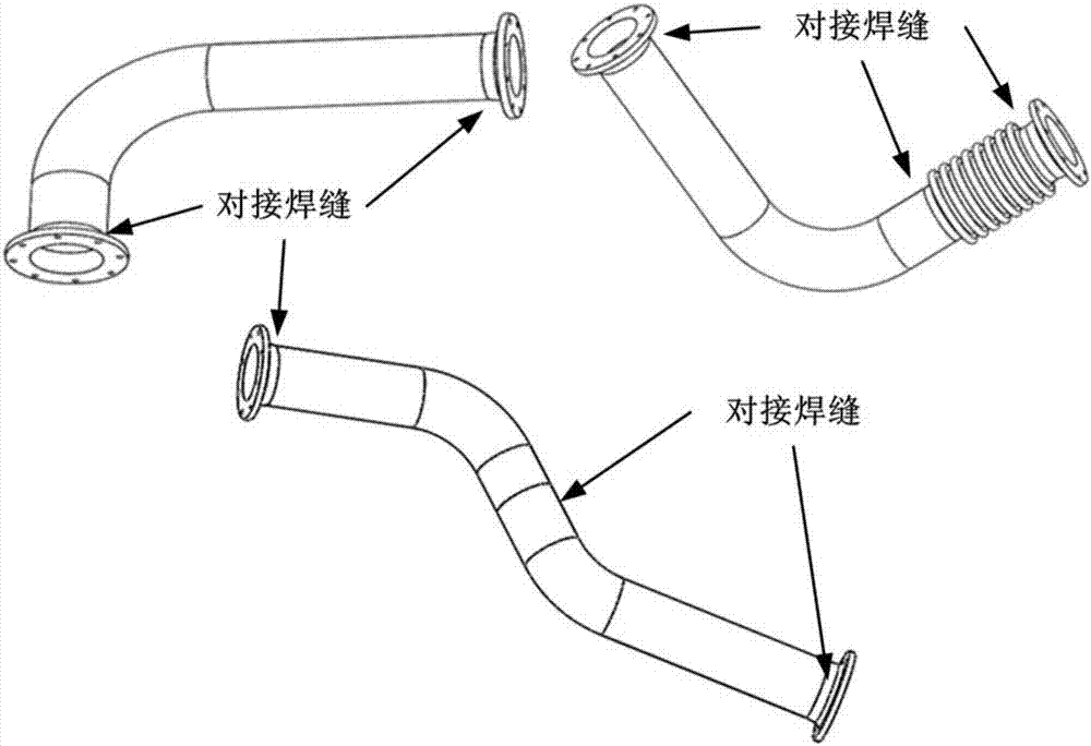
[0071] in such as Figure 5 For the catheter shown in , the specification of the catheter tube is Φ110×2.0mm, the length of the straight section at the A end is 400mm, the length of the straight section at the B end is 100mm, and the curved part is a right-angle bend with a bending radius of R200.
[0072] A clamping device suitable for elbow welding, the device mainly includes a rotating disc, a support mechanism, an adapter, a conduit snap ring, bolts and other connecting parts, such as Figure 4 shown.
[0073] The rotating disk is a disk with a diameter of Φ500mm and a thickness of 30mm. On the back of the disk there is a boss with a diameter of Φ50mm and a height of 100mm. The boss is clamped by the three-jaw chuck on the conventional welding positioner to realize the welding of the rotating disk and The installation of the positioner is fixed, and the welding positioner can be started during the welding process to realize that the rotating disc rotates with the main sha...
Embodiment 2
[0088] Such as Image 6 For the conduit shown in , the specification of the conduit pipe is Φ110×2.0mm, the length of the straight section at the A end is 400mm, the curved part is a right-angle bend with a bending radius of R200, and the length of the straight section at the B end is 100mm and is connected in the middle of the flange. 1 compensator, the size of the joint between the compensator and the pipe and the flange is Φ109×1.5mm, and the inner diameter of the joint is the same.
[0089] The clamping device used for elbow welding and clamping is exactly the same as that in Embodiment 1, and the steps of conduit clamping and welding by using the general device for elbow welding and clamping include:
[0090] (1) Prepare a conventional welding positioner, the welding positioner directly clamps the flange at the end A of the conduit to complete the welding of the circular seam between the pipe and the flange, and the welding positioner directly clamps the flange at the B e...
Embodiment 3
[0101] Such as Figure 7 For the conduit shown in , the conduit is welded by pipes at both ends and two flanges. The specifications of the pipes are Φ110×2.0mm. The part is a bend with a bending radius of R200 and a bending angle of 45°; the length of the straight line at the C end of the pipe at the right end is 100mm and the length of the straight line at the D end is 400mm, and the bending part is a bend with a bending radius of R200 and a bending angle of 45° Angle; the connection between the pipe and the pipe is the direct welding of the shorter straight section B and the straight section C, and the weld is not on the straight section at the end of the conduit.
[0102] The clamping device used for elbow welding and clamping is exactly the same as that of Embodiment 1, and the steps of conduit clamping and welding by using the general device for elbow welding and clamping include:
[0103] (1) Prepare a conventional welding positioner, fix the rotating disc on the weldin...
PUM
| Property | Measurement | Unit |
|---|---|---|
| Length | aaaaa | aaaaa |
| Diameter | aaaaa | aaaaa |
| Length | aaaaa | aaaaa |
Abstract
Description
Claims
Application Information