
Mechanical hand having space full-covering working capability

A technology with operating ability and full coverage, applied in manipulators, program-controlled manipulators, manufacturing tools, etc., can solve the problems of inability to expand and contract freely, small range of motion, poor adaptability to narrow spaces, etc. regulatory effect

Pending Publication Date: 2017-12-01
中国东方电气集团有限公司
View PDF7 Cites 18 Cited by
  • Summary
  • Abstract
  • Description
  • Claims
  • Application Information

AI Technical Summary

Problems solved by technology

However, the existing manipulators generally have 6 degrees of freedom, and their shoulder joints are fixed on the ground or moved relative to the bottom surface by rails. The range of motion is small, and it is impossible to achieve full-coverage motion in a wide range of spaces. At the same time, each joint is a revolving joint. , the end cannot be stretched freely, and the adaptability to narrow spaces is poor

Method used


Image

  • Mechanical hand having space full-covering working capability
  • Mechanical hand having space full-covering working capability
  • Mechanical hand having space full-covering working capability

Examples


Embodiment 1

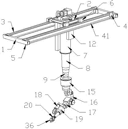
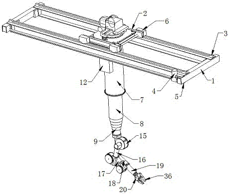
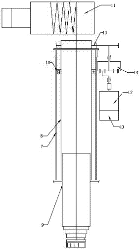
[0035] This embodiment, as the best embodiment of the present invention, discloses a manipulator with full space coverage operation capability, and its specific structure diagrams are shown in 1 and figure 2As shown, it includes a crane, a rotary telescopic cylinder and a mechanical arm. The crane includes a cart 1 and a trolley 2. The bottom of the cart 1 is provided with a cart traveling wheel 5, and the top of the cart 1 is provided with a track 3 and a motion motor 4. , the moving motor 4 is connected with the cart running wheel 5 through the transmission shaft 41, the track 3 is connected with the trolley 2 through the trolley traveling wheel 6, the trolley 2 is also provided with a movement motor 4, and the bottom of the trolley 2 is connected to the trolley. The rotary telescopic cylinder is connected, and the rotary telescopic cylinder includes a fixed cylinder 7, a rotary cylinder 8 and a telescopic cylinder 9. The fixed cylinder 8 is fixedly installed on the bottom o...

Embodiment 2

[0042] This embodiment is another preferred embodiment of the present invention, and its disclosed mechanical arm comprises shoulder joint 15, big arm 16, forearm 17 and wrist joint 18 connected in sequence, and its shoulder joint 15 is fixed with the end of telescopic tube 9 Connection, the end of the wrist joint 18 is connected with the end tool 20 through the connection head 35 .

[0043] The invention can accurately adjust the specific working position of the mechanical arm in the space through the coordinated movement of the cart and the trolley, and at the same time realizes the up and down movement of the mechanical arm in the space through the adjustment of the electric hoist and the gravity of the mechanical arm itself, thereby realizing The adjustment of the working position of the manipulator in the working space, while the manipulator has multiple degrees of freedom such as arm rotation, forearm rotation, forearm rotation, wrist rotation, wrist rotation, wrist exten...


PUM


Abstract

The invention discloses a mechanical hand having the space full-covering working capability. A large vehicle and a small vehicle cooperate to achieve the function of adjusting the working position of a mechanical arm at will in plane space, meanwhile, an electric block is used for achieving ascending movement of the mechanical arm, and the mechanical arm is driven to do the ascending movement. Due to sliding connection between a telescopic cylinder and a rotation cylinder, descending movement of the mechanical arm is achieved through gravity of the mechanical arm, and therefore large-range space position adjustment of the mechanical arm in the full-space range is achieved. Meanwhile, accurate adjustment of the working position is achieved through multiple freedom degrees of the mechanical arm. The rotation cylinder can do rotation movement in the plane relative to a fixed cylinder, and therefore the adaptability of the mechanical arm to the complex environment is improved, and the station adjusting accuracy of the mechanical arm is improved.

Description

technical field [0001] The invention relates to the technical field of industrial robots, in particular to a manipulator with full space coverage operation capability. Background technique [0002] A manipulator is an automatic operating device that can imitate certain actions of a human hand to grab, carry objects or operate tools according to a fixed program. It is characterized by being able to complete various expected operations through programming; the manipulator is the earliest Industrial robots are also the earliest modern robots. They can replace human heavy labor to realize mechanization and automation of production, and can operate in harmful environments to protect personal safety. Therefore, they are widely used in machinery manufacturing, metallurgy, electronics, light industry and Department of Atomic Energy etc. However, the existing manipulators generally have 6 degrees of freedom, and their shoulder joints are fixed on the ground or moved relative to the ...

Claims


Application Information

Patent Timeline
Patent Type & Authority Applications(China)
IPC IPC(8): B25J9/00
CPCB25J9/0018
Inventor 栗园园刘标官雪梅张帆莫堃董娜邓超于信宾
Owner 中国东方电气集团有限公司
Learn More