Motorized integrated anchoring chassis

A chassis and mooring technology, applied in balloon aircraft and other directions, can solve the problems of many required personnel, long deployment and erection time, construction and deployment difficulties, etc., to improve environmental adaptability and battlefield survivability, and to solve layout and transportation overruns , the effect of safe and reliable transportation

Inactive Publication Date: 2017-12-01
CHINA ELECTRONIC TECH GRP CORP NO 38 RES INST
View PDF9 Cites 2 Cited by
  • Summary
  • Abstract
  • Description
  • Claims
  • Application Information

AI Technical Summary

Problems solved by technology

However, the integration of traditional mobile aerostat mooring chassis systems is low. Due to the limitation of structural layout space and transportation, it is difficult to realize the integrated design of chassis equipment and slewing platform equipment. Field transportation is inconvenient
Secondly, the traditional mobile aerostat mooring chassis has a low degree of automation, takes a long time to deploy and erect, requires more staffing, and the chassis cannot be automatically leveled, which seriously restricts the combat efficiency of the system; in addition, the traditional positional The mooring system has high requirements on the working site, poor adaptability to the equipment site, difficult construction and deployment, many auxiliary tools and equipment, and is subject to the influence of the use environment such as regional curvature and terrain shielding

Method used


Image

  • Motorized integrated anchoring chassis
  • Motorized integrated anchoring chassis
  • Motorized integrated anchoring chassis

Examples


Embodiment

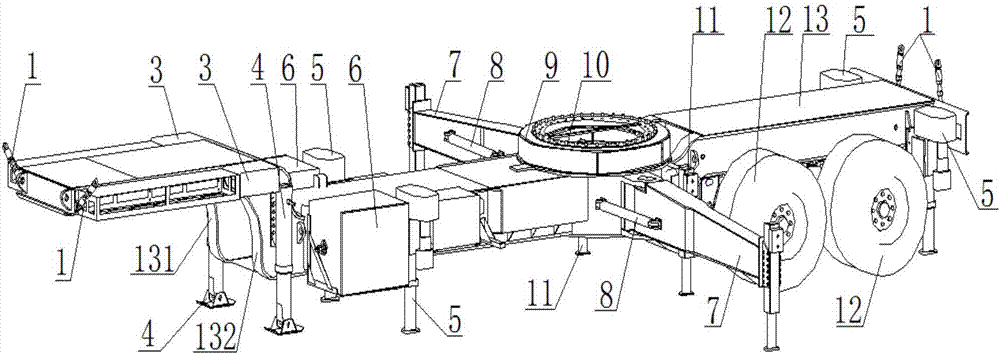
[0042] see figure 1 , a motorized integrated mooring chassis, including four locking screws 1, two accessory boxes 3, two front legs 4, four self-leveling legs 5, two cable boxes 6, two overturning braces Leg 7, two support leg fixing rods 8, protective cover 9, slewing bearing 10, two load-bearing support legs 11, axle tire 12 and chassis longitudinal beam 13.

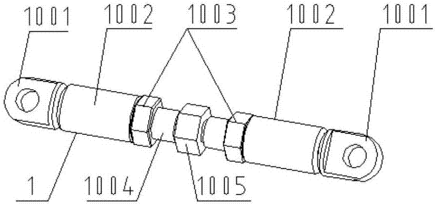
[0043] see figure 2 , the locking screw 1 includes two single ears 1001 , two sleeves 1002 , two limit nuts 1003 , screw rod 1004 , and fixed nut 1005 . Both ends of the locking screw 1 are respectively connected with a single ear 1001, one end of the single ear 1001 is a cylindrical member with external thread, and the other end is a single fork ear structure with a round hole in the center. The sleeve 1002 is a round pipe structure with internal thread, which is used to connect and fix the external thread of the single ear 1001. The limit nut 1003 is installed on the threaded rod 1004 for limiting and fixing the...


PUM


Abstract

The invention discloses a motorized integrated anchoring chassis. The motorized integrated anchoring chassis comprises locking screws, fixed lug pieces, accessory boxes, front supporting legs, automatic leveling supporting legs, cable boxes, overturning supporting legs, supporting leg fixing rods, a protective cover, a slewing bearing, bearing supporting legs, axle tires and a chassis longitudinal beam. The front supporting legs, the automatic leveling supporting legs, the two overturning supporting legs and the bearing supporting legs can be folded when the motorized integrated anchoring chassis is transported, and the overturning supporting legs are folded in the direction of a tractor. According to the motorized integrated anchoring chassis, the platform functionality, the maintainability and man-machine engineering are integrated, and integrated design, environmental adaptability design, rapid expansion erection design, automatic leveling design and safety design are conducted; the high motorizing performance of the anchoring chassis and reliable integrating of a slewing upper tool and the anchoring chassis are achieved; the erection and deployment time is effectively saved; and the working efficiency is improved.

Description

technical field [0001] The invention belongs to the ground mooring field of tethered balloons, and in particular relates to a mobile integrated mooring chassis. Background technique [0002] With the continuous development of modern electronic information technology, the improvement of the degree of communication integration, and the complex and changeable combat environment, tethered balloons need to be moored and moored quickly in the combat command field in complex areas and quickly launched into the air. Balloons have high requirements for maneuverability, mooring stability, reliability and safety. The mobile integrated mooring chassis is the ground working platform of the mobile tethered balloon system, which is used to carry and support the mooring slewing top-loading system, and realize ground mooring, air mooring, lift-off and descent recovery of the tethered balloon. However, the integration of traditional mobile aerostat mooring chassis systems is low. Due to the ...

Claims


Application Information

Patent Timeline
Patent Type & Authority Applications(China)
IPC IPC(8): B64B1/56
Inventor 李浩王军李岩吴斌王平安王志海张志富高山陶海峰仝允
Owner CHINA ELECTRONIC TECH GRP CORP NO 38 RES INST
Why Eureka
Try Eureka