Connective pneumatic conveyor

A pneumatic conveyor and one-piece technology, applied in the field of pneumatic conveying, can solve the problems of large space requirements for belt conveyors and rotary conveyors, poor site sanitation, and heavy maintenance workload.

Pending Publication Date: 2017-12-01
HUANENG CLEAN ENERGY RES INST +1
View PDF14 Cites 2 Cited by
  • Summary
  • Abstract
  • Description
  • Claims
  • Application Information

AI Technical Summary

Problems solved by technology

[0005] At present, belt conveyors or screw conveyors are generally used as biomass and solid waste incineration feeding devices. However, belt conveyors have many moving parts and vulnerable parts, and the usual maintenance workload is relative

Method used


Image

  • Connective pneumatic conveyor
  • Connective pneumatic conveyor
  • Connective pneumatic conveyor

Examples


Embodiment Construction

[0021] The present invention will be described in further detail below in conjunction with the accompanying drawings.

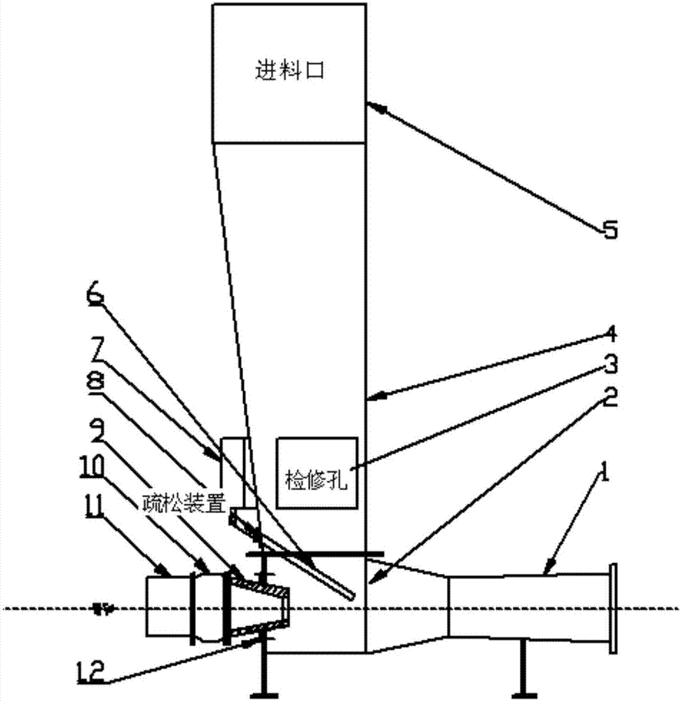
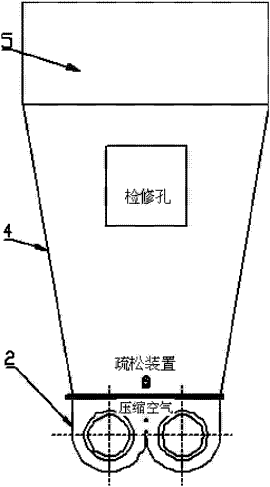
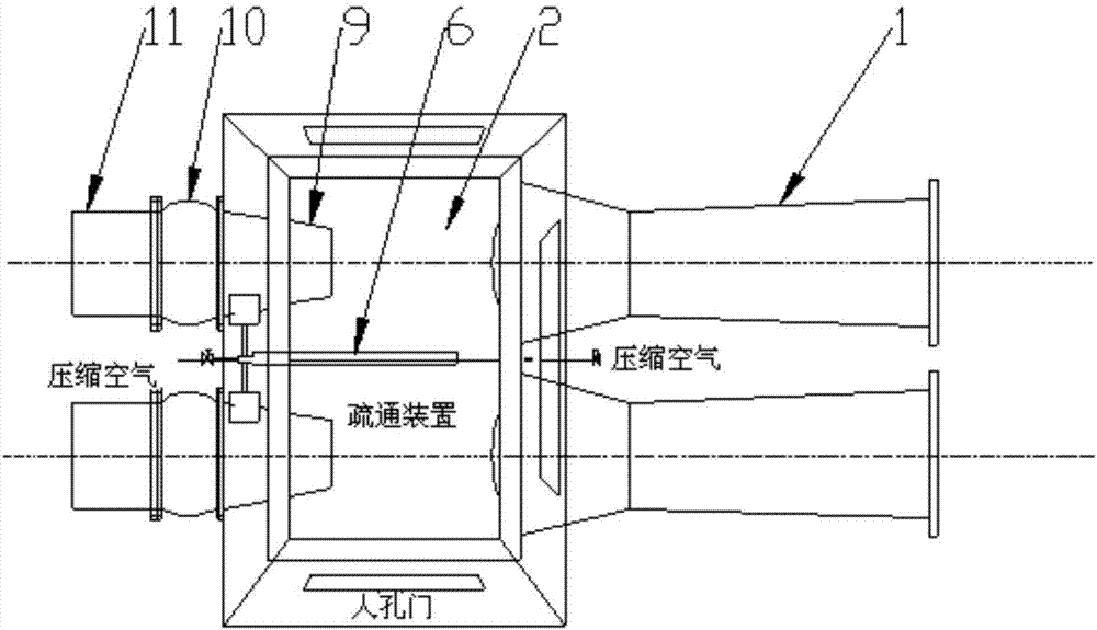
[0022] see figure 1 figure 2 , a conjoined pneumatic conveyer provided by the present invention, comprising: a conjoined conveying chamber body 2 and an associated accelerating nozzle 9, an expansion and boosting section 1, a loosening device, and a buffer chamber 4. The conjoined conveying The outlet of the bin body 2 is arranged with an expansion and boosting section 1, the inlet of the one-piece delivery bin body 2 is arranged with an acceleration nozzle 9, and the upper part of the one-piece delivery bin body 2 is arranged with a buffer bin 4, and the lower part of the buffer bin 4 is A loosening device is provided, and a feeding port 5 is arranged on the upper part of the buffer bin.

[0023] Further, the expansion and boosting section 1 is a structure with increasing cross-sectional area;

[0024] Further, the acceleration nozzle 9 is connected to t...


PUM


Abstract

A connective pneumatic conveyor comprises a feeding port; a buffer cabin is arranged below the feeding port; a connective conveying cabin body is arranged at the bottom of the buffer cabin; the buffer cabin and the connective conveying cabin body are arranged perpendicularly and communicate with each other; an accelerating gas spraying device is arranged at the gas inlet position of a channel of the connective conveying cabin body; an expanding and boosting section is arranged at the gas outlet position of the connective conveying cabin body; a loosening device is arranged in the connection position of the buffer cabin and the connective conveying cabin body, and crushed biomass and solid waste enter the buffer cabin through the feeding port and then are dispersed and enter the connective conveying cabin body under the action of a material deflector rod on the lower part of the buffer cabin; and the materials are carried under the action of high-speed gas flow at the accelerating nozzle outlet to enter the expanding and boosting section, and then are conveyed through a conveying pipeline to an existing large-sized boiler for blending combustion utilization. The connective pneumatic conveyor has the advantages of simple structure, wide conveying material adaptability, difficulty in bridging, large conveying quantity, convenience in arrangement, capability of continuously operating, convenience in disassembling, repair and maintenance, excellent operating environment and the like.

Description

technical field [0001] The invention relates to the technical field of pneumatic conveying, in particular to a one-piece pneumatic conveying device. Background technique [0002] Biomass mainly refers to lignocellulose (lignin for short) such as straw and trees other than grain and fruit in the process of agricultural and forestry production, leftovers of agricultural product processing, agricultural and forestry waste, and poultry manure and waste in the process of animal husbandry. matter etc. Biomass energy is an important part of renewable energy. The efficient development and utilization of biomass energy will play a very positive role in solving energy and ecological environment problems. [0003] Solid waste refers to the solid and semi-solid waste materials that pollute the environment and are discarded because of human production, construction, daily life and other activities, which cannot be used at a certain time and place. Municipal solid waste is generally div...

Claims


Application Information

Patent Timeline
IPC IPC(8): B65G53/50
CPCB65G53/50
Inventor 张世鑫刘海峰赵鹏勃袁野高洪培王鹏利王海涛陈宇肇许燕飞骆顺花钟绍松蔡芳龙魏晓晖叶荣志赖建梅曾方徐敏航侯林海陈玉洪吕勇
Owner HUANENG CLEAN ENERGY RES INST
Why Eureka
Try Eureka