Rotary air floatation tank

An air flotation tank, rotary technology, applied in flotation water/sewage treatment, energy wastewater treatment, water/sewage treatment, etc., can solve the problems of affecting filtration steps, uneven reaction, increased mud content, etc., and achieve extended use. Longevity, easy to mix evenly, and the effect of reducing mud content

Active Publication Date: 2017-12-01
CAMBRIDGE ENVIRONMENTAL CHINA CO LTD
View PDF9 Cites 2 Cited by
  • Summary
  • Abstract
  • Description
  • Claims
  • Application Information

AI Technical Summary

Problems solved by technology

[0004] Although the development of air flotation and dissolved air equipment and slag scraping machine is very mature, there are still some minor problems in the whole air flotation step, such as during the dosing reaction, because the water flow is in a flowing state during the whole process of the air flotation step, Therefore, there are generally phenomena of insufficient stirring, uneven reaction, or too violent stirring that leads to the decomposition of flocs. For example, the scum located under the slag guide plate is difficult t

Method used


Image

  • Rotary air floatation tank
  • Rotary air floatation tank
  • Rotary air floatation tank

Examples


Embodiment Construction

[0038] The present invention will be further described in detail below in conjunction with the accompanying drawings, so that those skilled in the art can implement it with reference to the description.

[0039] In the description of the present invention, the orientations or positional relationships indicated by the terms "transverse", "upper", "lower", "top", "bottom", "inner", "outer" etc. are based on the orientations shown in the drawings Or positional relationship is only for the convenience of describing the present invention and simplifying the description, and does not indicate or imply that the referred device or element must have a specific orientation, be constructed and operated in a specific orientation, and therefore should not be construed as a limitation of the present invention.

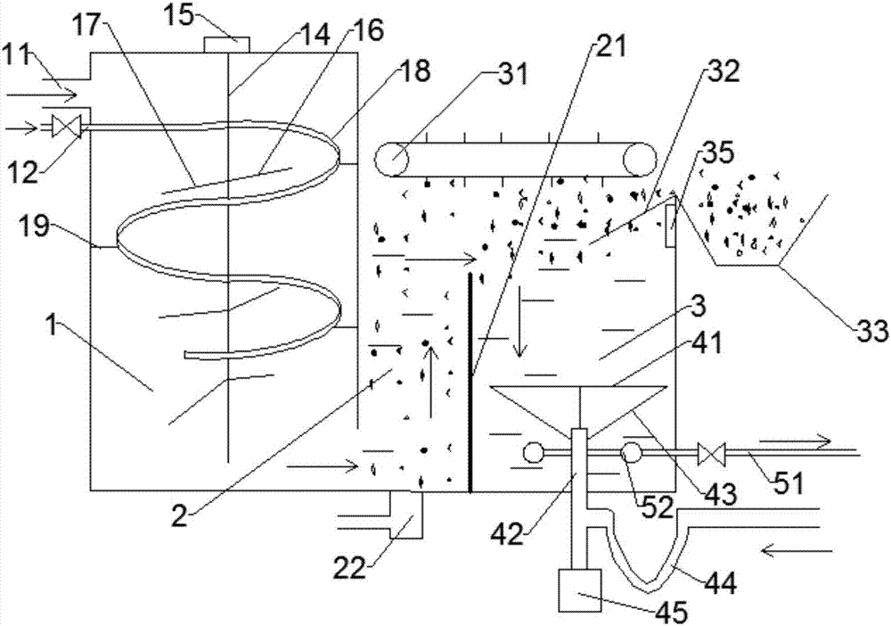
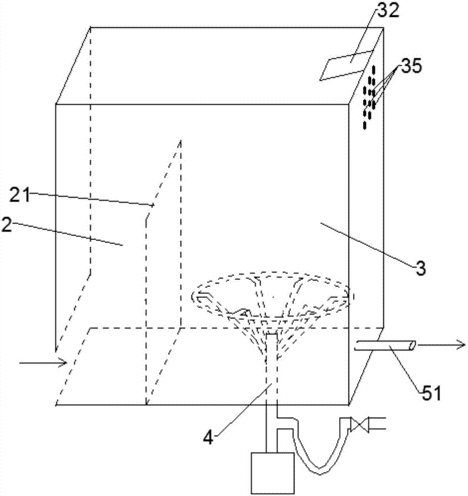
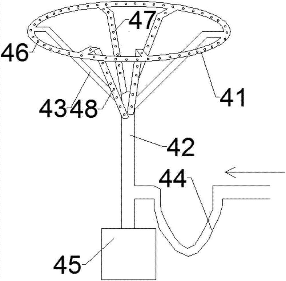
[0040] Such as Figure 1~3 As shown, the present invention provides a rotary air flotation pool, comprising:

[0041] Reaction tank 1, its upper end is provided with raw water inle...


PUM


Abstract

The invention discloses a rotary air floatation tank. The rotary air floatation tank comprises a reaction tank, wherein a raw water inlet and a drug inlet are formed in the upper end of the reaction tank; a raw water outlet is formed in the lower end of the reaction tank; the reaction tank is internally provided with a first stirring device; the first stirring device comprises a stirring shaft which is vertically arranged, multiple groups of stirring blades which are fixedly arranged on the stirring shaft and a first motor which is used for driving the stirring shaft to rotate; a controller is used for controlling the first motor to drive the stirring shaft to forwards rotate by two circles at first and then reversely rotate by two circles so as to do periodic reciprocating rotation; a contact separation tank is located at the downstream of the reaction tank; the lower side of the contact separation tank is communicated with the raw water outlet; the contact separation tank is internally provided with a baffle plate; the baffle plate is used for separating the contact separation tank into a contact zone in the upstream and a separation zone in the downstream; the separation zone comprises a slag removing assembly, a rotating assembly and a water draining assembly. The rotary air floatation tank disclosed by the invention has the beneficial effects that mixing of a coagulant and raw water is quickened, scum in a dead corner of a slag guiding plate and under the separation zone can be cleaned in time, the silt content of clear water is greatly reduced, the purpose of saving the volume of a filter layer is achieved, and the service life of the filter layer is prolonged.

Description

technical field [0001] The invention relates to the field of sewage treatment. More specifically, the present invention relates to a rotary air flotation tank. Background technique [0002] Sewage treatment technology mainly includes the following steps, pretreatment, coagulation and sedimentation, flotation and air flotation, filtration, redox, activated carbon adsorption, and membrane separation. Among them, flotation is mainly treated by natural flotation devices to separate substances with a specific gravity lower than water, such as oil. , and the substance with a specific gravity greater than water is processed by an air flotation device. The principle is that the fine air bubbles first adhere to the suspended particles in the water to form a "bubble-particle" complex with an overall density lower than that of water, so that the suspended particles float together with the air bubbles. Raise to the surface of the water, and then scrape off the scum with a scum scraper ...

Claims


Application Information

Patent Timeline
IPC IPC(8): C02F1/24C02F1/52
CPCC02F1/24C02F1/52C02F2201/002Y02W10/33
Inventor 韦爱龄
Owner CAMBRIDGE ENVIRONMENTAL CHINA CO LTD
Why Eureka
Try Eureka