Burying equipment for underground drainage pipe
A drainage pipe and equipment technology, applied in the field of drainage pipe installation equipment, can solve the problems of placing in the required position, low labor efficiency, and difficulty in draining pipes, etc.
- Summary
- Abstract
- Description
- Claims
- Application Information
AI Technical Summary
Problems solved by technology
Method used
Image

Examples
Embodiment 1
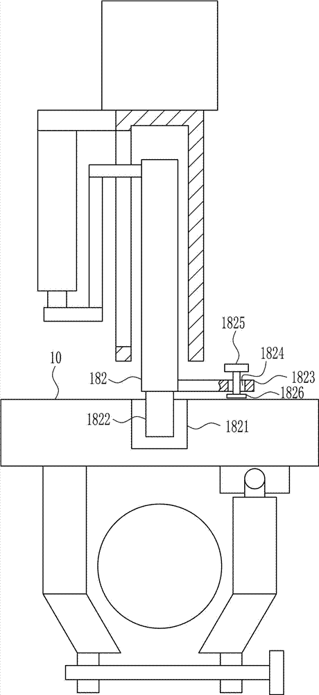
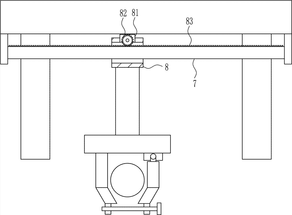
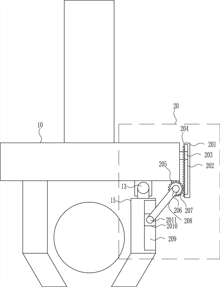
[0038] A buried device for underground drainage pipes, such as Figure 1-8 As shown, it includes a mounting plate 1, a supporting plate 2, a first connecting block 3, a first rotating shaft 4, a tire 5, a fixing block 6, a guide rail 7, a guide sleeve 8, a connecting rod 9, a fixing plate 10, and a first splint 11 , the first support seat 12, the second rotating shaft 13, the rotating block 14, the second clamping plate 15, the first nut 16 and the first screw rod 17, the support plate 2 is installed on the four sides of the lower side of the mounting plate 1 by welding The lower end of the support plate 2 is installed with a first connecting block 3 by welding, and the first connecting block 3 is rotatably connected to the first rotating shaft 4 on the outside and below, and the tire 5 is connected to the first rotating shaft 4. The left and right sides of the mounting plate 1 are two The fixed block 6 is installed on the side by welding, the guide rail 7 is installed by weld...
Embodiment 2
[0040] A buried device for underground drainage pipes, such as Figure 1-8 As shown, it includes a mounting plate 1, a supporting plate 2, a first connecting block 3, a first rotating shaft 4, a tire 5, a fixing block 6, a guide rail 7, a guide sleeve 8, a connecting rod 9, a fixing plate 10, and a first splint 11 , the first support seat 12, the second rotating shaft 13, the rotating block 14, the second clamping plate 15, the first nut 16 and the first screw rod 17, the support plate 2 is installed on the four sides of the lower side of the mounting plate 1 by welding The lower end of the support plate 2 is installed with a first connecting block 3 by welding, and the first connecting block 3 is rotatably connected to the first rotating shaft 4 on the outside and below, and the tire 5 is connected to the first rotating shaft 4. The left and right sides of the mounting plate 1 are two The fixed block 6 is installed on the side by welding, the guide rail 7 is installed by weld...
Embodiment 3
[0043] A buried device for underground drainage pipes, such as Figure 1-8 As shown, it includes a mounting plate 1, a supporting plate 2, a first connecting block 3, a first rotating shaft 4, a tire 5, a fixing block 6, a guide rail 7, a guide sleeve 8, a connecting rod 9, a fixing plate 10, and a first splint 11 , the first support seat 12, the second rotating shaft 13, the rotating block 14, the second clamping plate 15, the first nut 16 and the first screw rod 17, the support plate 2 is installed on the four sides of the lower side of the mounting plate 1 by welding The lower end of the support plate 2 is installed with a first connecting block 3 by welding, and the first connecting block 3 is rotatably connected to the first rotating shaft 4 on the outside and below, and the tire 5 is connected to the first rotating shaft 4. The left and right sides of the mounting plate 1 are two The fixed block 6 is installed on the side by welding, the guide rail 7 is installed by weld...
PUM
 Abstract
Description
Claims
Application Information
 - R&D
- Intellectual Property
- Life Sciences
- Materials
- Tech Scout
- Unparalleled Data Quality
- Higher Quality Content
- 60% Fewer Hallucinations
Browse by: Latest US Patents, China's latest patents, Technical Efficacy Thesaurus, Application Domain, Technology Topic, Popular Technical Reports.
© 2025 PatSnap. All rights reserved.Legal|Privacy policy|Modern Slavery Act Transparency Statement|Sitemap|About US| Contact US: help@patsnap.com