Relay protection circuit integrity tester

A relay protection and relay circuit technology, applied in the field of relay protection circuit integrity tester, can solve the problems of insufficient backup pressure plate, difficult construction, increase the running time of the line without main protection, etc., so as to improve work efficiency and reduce workload Effect

Active Publication Date: 2017-12-01
广东电网有限责任公司惠州供电局
View PDF5 Cites 5 Cited by
  • Summary
  • Abstract
  • Description
  • Claims
  • Application Information

AI Technical Summary

Problems solved by technology

[0003] 1. Construction difficulties
[0004] The requirement of this control measure for the protective screen cabinet is to have spare pressure plates. Taking Beijing Sifang as an example, there must be at least four spare pressure plates, a...

Method used


Image

  • Relay protection circuit integrity tester
  • Relay protection circuit integrity tester
  • Relay protection circuit integrity tester

Examples


Embodiment 1

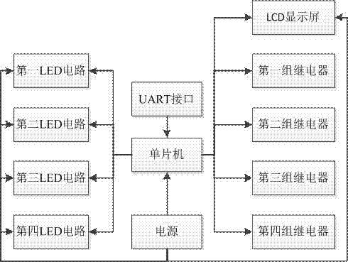
[0054] like figure 1 As shown, a relay protection circuit integrity tester includes a single-chip microcomputer, a power supply, an LCD display, a first group of relays, a second group of relays, a third group of relays, a fourth group of relays, a first LED circuit, a second LED circuit, third LED circuit, fourth LED circuit and UART interface, wherein,

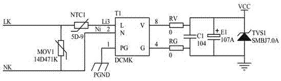
[0055] The power supply is electrically connected to the microcontroller, and the circuit diagram of the power supply is as follows: figure 2 As shown, the power supply circuit includes a power supply chip, a transient voltage diode, a thermistor, a varistor and a capacitor, and the transient voltage diode and the power supply chip are electrically connected in parallel; the thermistor and the power supply chip are electrically connected in series ; The piezoresistor is electrically connected to the power supply chip in parallel.

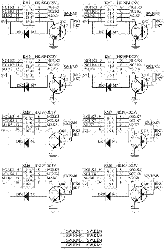
[0056] Each group of relays includes 2 relays, and the control terminals of the 2 relay cir...

Embodiment 1

[0060] Embodiment 1 workflow:

[0061] Embodiment 1 and Beijing Sifang CSC-101 and CSC-102 receive schematic diagrams such as Figure 7 shown;

[0062] Example 1 and the schematic diagram of Beijing Sifang CSC-101 and CSC-102 sending letters are as follows Figure 8 shown;

[0063] The four groups of relays (K1, K2, K3, K4) in Example 1 are electrically connected to phase A, phase B, phase C and the triple jump phase respectively, and two relays in each group are electrically connected to receiving and sending respectively. The four LED circuits correspond to one of the relays respectively. A group of relays work, and the corresponding LED circuit lights up. The single-chip microcomputer independently controls the contact / breakpoint action of each group of relays, and the time to maintain the corresponding action. Combining the indicators, input and output of the relay protection circuit, observe the integrity of the relay protection circuit. The LCD display is used to d...

Embodiment 2

[0065] like figure 1 As shown, a relay protection circuit integrity tester includes a single-chip microcomputer, a power supply, an LCD display, a first group of relays, a second group of relays, a third group of relays, a fourth group of relays, a first LED circuit, a second LED circuit, third LED circuit, fourth LED circuit and UART interface, wherein,

[0066] The power supply is electrically connected to the microcontroller, and the circuit diagram of the power supply is as follows: figure 2 As shown, the power supply circuit includes a power supply chip, a transient voltage diode, a thermistor, a varistor and a capacitor, and the transient voltage diode and the power supply chip are electrically connected in parallel; the thermistor and the power supply chip are electrically connected in series ; The piezoresistor is electrically connected to the power supply chip in parallel.

[0067] Each group of relays includes 2 relays, and the control terminals of the 2 relay cir...


PUM


Abstract

The invention discloses a relay protection circuit integrity tester comprising a microprocessing chip and a relay detection module; the relay detection module is electrically connected with a relay protector; the relay detection module contact/breakpoint motions are combined with a relay protection loop indication lamp, input and output, thus detecting the relay protection loop integrity; the relay detection module is electrically connected with the microprocessing chip. The tester is applied in the following steps: 1, the relay detection module is electrically connected with the relay protector; 2, the microprocessing chip controls the relay detection module to make contact/breakpoint motions, and controls the contact/breakpoint motion duration times; 3, the relay protection loop indication lamp, input and output are considered, thus observing the relay protection loop integrity. The tester can singly control the relay contact/breakpoint motions of a random phase, and can keep the time duration of the corresponding motions; the relay protection circuit integrity tester can control the relay motions, thus mitigating working personnel workloads, and improving the working efficiency.

Description

technical field [0001] The invention relates to the field of relay protection electrical devices, in particular to a relay protection circuit integrity tester. Background technique [0002] The existing method for detecting the switching effect of the channel switching handle is to add a test pressure plate through the protection screen, and simulate the relevant relay action of the protection device by switching the pressure plate back and forth to test. For a line with a bypass on only one side of the line, add two test circuits of "line protection sending" and "bypass protection sending" on the side with bypass; add a test circuit of "line protection sending" on the opposite side ; For lines with bypasses on both sides of the line: two test circuits of "line protection sending" and "bypass protection sending" need to be added on both sides. Add a test pressure plate through the protective screen, and check the integrity of the circuit by switching the pressure plate back...

Claims


Application Information

Patent Timeline
IPC IPC(8): G01R31/28
CPCG01R31/2827
Inventor 孙迪飞罗振华王英民李伟强郑兆典邵小斌郭德孺梁景棠
Owner 广东电网有限责任公司惠州供电局
Why Eureka
Try Eureka