
Dual-salient-pole motor with permanent magnets positioned between stator poles and rotor poles

A double salient pole motor and stator pole technology, applied in the direction of magnetic circuit rotating parts, magnetic circuit, synchronous machine, etc., can solve the problems of long current commutation time, increase of effective air gap length, etc., to improve torque performance, Increased effective area and reduced torque ripple

Inactive Publication Date: 2017-12-01
HUAZHONG UNIV OF SCI & TECH
View PDF4 Cites 5 Cited by
  • Summary
  • Abstract
  • Description
  • Claims
  • Application Information

AI Technical Summary

Problems solved by technology

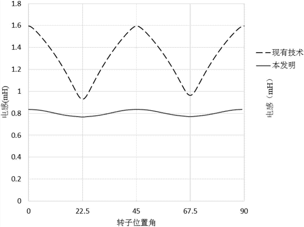
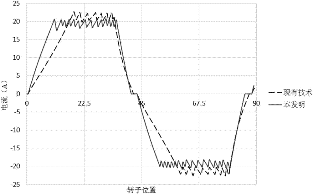
[0004] Aiming at the above defects or improvement needs of the prior art, the present invention provides a doubly salient pole motor in which the permanent magnets are located at the tops of the teeth of the stator poles. By arranging the permanent magnets between the stator poles and the rotor poles, the stator poles and the rotor poles The effective air gap length between them is increased, thereby solving the technical problem of long current commutation time caused by the large armature winding inductance

Method used


Image

  • Dual-salient-pole motor with permanent magnets positioned between stator poles and rotor poles
  • Dual-salient-pole motor with permanent magnets positioned between stator poles and rotor poles
  • Dual-salient-pole motor with permanent magnets positioned between stator poles and rotor poles

Examples


Embodiment Construction

[0031] In order to make the object, technical solution and advantages of the present invention clearer, the present invention will be further described in detail below in conjunction with the accompanying drawings and embodiments. It should be understood that the specific embodiments described here are only used to explain the present invention, not to limit the present invention. In addition, the technical features involved in the various embodiments of the present invention described below can be combined with each other as long as they do not constitute a conflict with each other.

[0032] figure 1 (a)-(c) are structural schematic diagrams of a doubly salient pole motor in which the permanent magnets are located at the top of the stator pole teeth constructed according to the preferred embodiment of the present invention; figure 1 (a) A permanent magnet is arranged on a stator pole, and the magnetization directions of the two permanent magnets on the same set of stator pol...


PUM

PropertyMeasurementUnit
Angleaaaaaaaaaa
Angleaaaaaaaaaa

Abstract

The invention belongs to the field of a dual-salient-pole permanent magnet motor, and discloses a dual-salient-pole motor with permanent magnets positioned between stator poles and rotor poles. The dual-salient-pole motor comprises a stator, a rotor, a rotary shaft, the permanent magnets and armature windings; multiple salient-pole-structured stator poles are arranged on the stator; the armature windings are wound around a group of stator poles; uniformly distributed salient-pole-structured rotor poles are arranged on the rotor; the permanent magnets are arranged on the stator poles and positioned between the stator poles and the rotor poles for improving air gap flux density between the stator and the rotor; the rotary shaft is arranged in the rotor; and when the armature windings are input with current, the magnetic field generated by the armature windings and the electric field generated by the permanent magnets are in interaction, so as to enable the rotor and the rotary shaft to be in rotational motion relative to the stator. By virtue of the dual-salient-pole motor, the air gap flux density between the stator poles and the rotor poles can be improved; and meanwhile, the magnetic resistance of the magnetic paths of the armature windings is improved, the winding inductance, the motor time constant and the current reversing time are lowered, the current reversing performance and the torque output performance are improved, and torque pulsation is lowered.

Description

technical field [0001] The invention belongs to the field of doubly salient pole permanent magnet motors, and more specifically relates to a doubly salient pole motor in which permanent magnets are located on tops of stator pole teeth. Background technique [0002] In recent years, doubly salient pole motors in which both the stator poles and the rotor poles are salient poles have been extensively studied. In order to increase the torque and power density of an electrically excited doubly salient motor and improve the torque output performance, permanent magnets are introduced into the doubly salient motor in the prior art to form a doubly salient permanent magnet synchronous motor. [0003] In order to further improve the torque performance of the doubly salient permanent magnet synchronous motor, the existing technology obtains the bipolar flux linkage by changing the winding connection mode, thereby improving its torque and power density to a certain extent, but this pole...

Claims


Application Information

Patent Timeline
IPC IPC(8): H02K21/38H02K1/14H02K1/17H02K1/24
CPCH02K21/38H02K1/14H02K1/17H02K1/24H02K2201/03H02K2213/03
Inventor 徐伟何明杰叶才勇
Owner HUAZHONG UNIV OF SCI & TECH
Learn More