
Casing structure with leaf apex interval control and leaf tip flow control

A technology of flow control and blade tip clearance, which is applied in the direction of engine components, machines/engines, mechanical equipment, etc., can solve the problems of blade tip leakage loss, large thermal expansion deformation, etc., to reduce leakage loss, easy processing, and reduce diameter effect on deformation

Active Publication Date: 2017-12-05
NORTHWESTERN POLYTECHNICAL UNIV
View PDF7 Cites 14 Cited by
  • Summary
  • Abstract
  • Description
  • Claims
  • Application Information

AI Technical Summary

Problems solved by technology

[0005] The technical problem to be solved by the present invention is: the purpose of the present invention is to propose a casing structure for blade tip clearance control and blade tip flow control to solve the problems of large thermal expansion deformation of the existing turbine casing and serious leakage loss of the blade tip

Method used


Image

  • Casing structure with leaf apex interval control and leaf tip flow control
  • Casing structure with leaf apex interval control and leaf tip flow control
  • Casing structure with leaf apex interval control and leaf tip flow control

Examples


Embodiment Construction

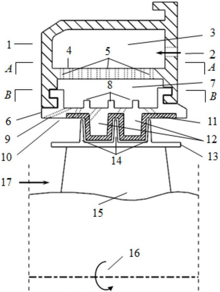
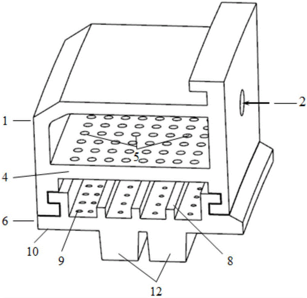
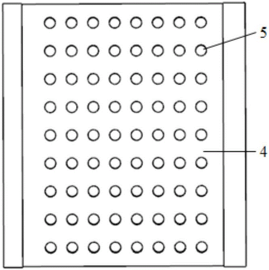
[0022] see Figure 1-Figure 5 , the present invention proposes a novel turbine case structure, and its technical solution is as follows: The present invention discloses a case structure with blade tip clearance control and blade tip flow control, which mainly includes a turbine case, a cooling structure inside the case, and a turbine outer casing. The ring seal structure; the internal cooling structure of the casing defines the cold air intake hole, the impact hole and the impact plate structure, the impact plate and the turbine casing form the first chamber, and a plurality of impact holes are defined on the impact plate; the outer ring of the turbine passes through The coupling mode is connected to the turbine casing structure, which forms a second chamber with the impact plate, and the outer ring defines a plurality of spoiler structures, air film hole structures and anti-leakage structures; the cold air flow enters the first chamber through the air intake hole. The chamber...


PUM


Abstract

The invention discloses a casing structure with leaf apex interval control and leaf tip flow control. A turbine casing and an impact plate form a first cavity, multiple impact holes are limited in the impact plate, a turbine outer ring form a second cavity, multiple turbulent structures, and an air film hole structure and a leak-proof structure are limited on the outer ring; cold air flow enters the first cavity through an air incoming hole, enters the second cavity through an impact hole structure to impact the outer ring, fully cools the turbine outer ring through the turbine structures and flows out from the air film hole structure of the outer ring to form a cooling air film to be finally mixed with main fuel gas; a boss structure on the turbine outer ring is mainly used for blocking formation and development of leaf tip leakage vortex. Heat exchange effect of cooling airflow inside the casing is enhanced, the air film hole structure has good cooling effect on the surface of the turbine casing and a leaf tip position in direct contact with high-temperature fuel gas, the leakage-proof structure effectively lowers leaf tip leakage loss, and turbine efficiency is improved.

Description

technical field [0001] The invention relates to a turbine casing structure, in particular to a casing structure with blade tip clearance control and blade top flow control applicable to machinery such as aero-engines and gas turbines. Background technique [0002] With the continuous improvement of gas turbine performance, the inlet temperature of the turbine continues to increase, and more efficient and advanced cooling technologies are urgently needed to ensure the normal operation of high-temperature components of the gas turbine. As one of the high-temperature components, the turbine casing is directly in contact with the mainstream gas, and the working conditions are harsh. The high-temperature resistance of the material alone cannot withstand high-temperature erosion for a long time; at the same time, the turbine casing expands and deforms under the action of high temperature. As a result, the blade tip clearance becomes larger, which seriously affects the turbine effi...

Claims


Application Information

Patent Timeline
Patent Type & Authority Applications(China)
IPC IPC(8): F01D11/08F01D25/12F01D25/24F01D25/00
CPCF01D11/08F01D25/00F01D25/12F01D25/24
Inventor 仝福娟李磊高文静孙守义唐仲豪李亚东苟文选岳珠峰
Owner NORTHWESTERN POLYTECHNICAL UNIV
Learn More