Unconventional layout form air intake and exhaust pipeline device

An unconventional air intake and exhaust technology, which is applied in measuring devices, aerodynamic tests, instruments, etc., can solve the problem that the ejector-type air intake and exhaust pipelines cannot reach the air intake and exhaust analog values, and the aerodynamic stripping of the whole machine and other problems, to achieve the effect of good air tightness, stable operation and strong operability

Active Publication Date: 2017-12-05
中国航空工业集团公司哈尔滨空气动力研究所
View PDF12 Cites 10 Cited by
  • Summary
  • Abstract
  • Description
  • Claims
  • Application Information

AI Technical Summary

Problems solved by technology

These structural features pose a great challenge to the wind tunnel test, especially the second layout mentioned above. If the turbine power simulator (TPS) is used as the dynamic simulation device, it is difficult to combine the influence of the internal pipeline of the model with the aerodynamic force of the whole machine. The stripping is very good, but the ejector-type intake and exhaust pipelines of the conventional layout cannot reach the intake and exhaust analog value required by the test

Method used


Image

  • Unconventional layout form air intake and exhaust pipeline device
  • Unconventional layout form air intake and exhaust pipeline device
  • Unconventional layout form air intake and exhaust pipeline device

Examples


Embodiment 1

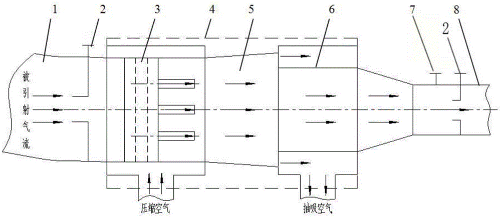
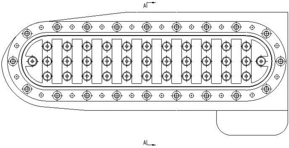
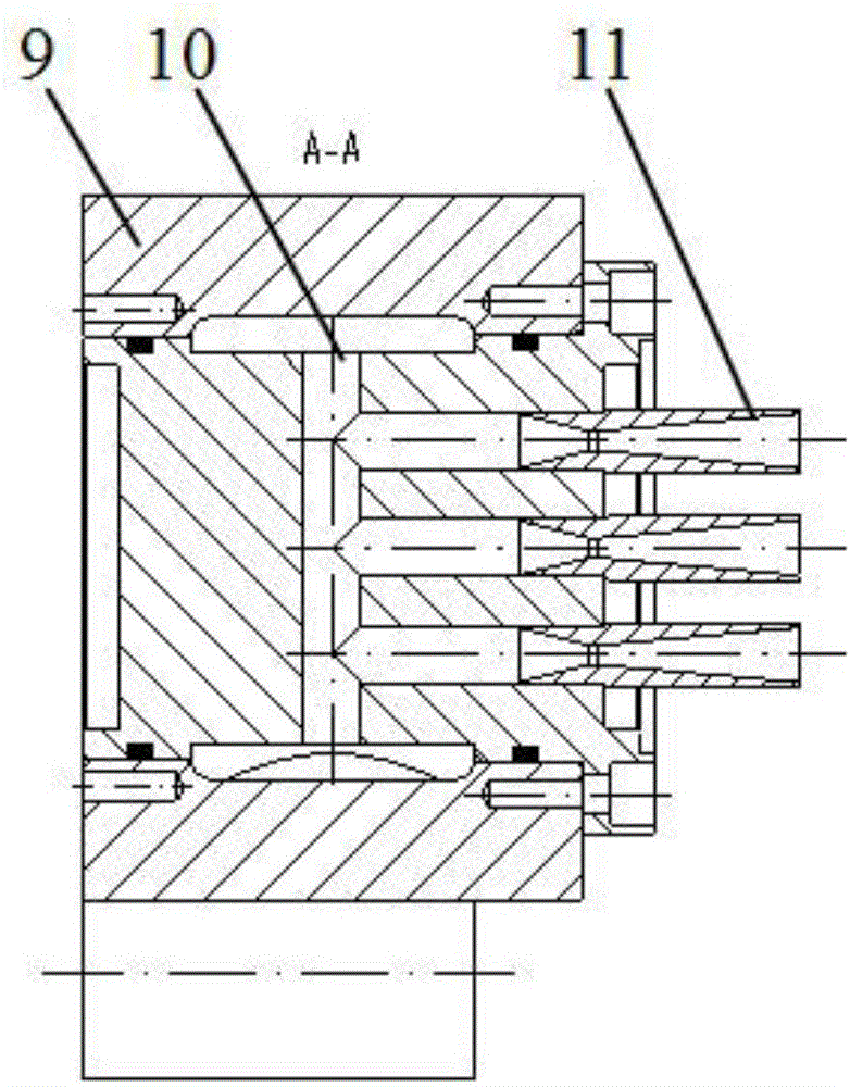
[0018] combine Figure 1-4 As shown, an intake and exhaust pipeline device with an unconventional layout, including an intake duct 1, two pressure sensors 2, an ejector 3, a core support member 4 inside the model, a diffuser tube 5, and a bypass suction pipeline 6. The temperature sensor 7 and the exhaust nozzle 8, the ejector 3, the diffuser pipe 5 and the bypass suction pipeline 6 are installed in the core support 4 inside the model, the air inlet 1 is connected with the ejector 3, and the ejector The diffuser 3 is connected with the diffuser 5, the diffuser 5 is connected with the bypass suction pipeline 6, and the bypass suction pipeline 6 is connected with the tail nozzle 8, the ejected air flow enters from the air inlet 1, and the compressed air enters from the induced The injector 3 enters, the bypass suction pipeline 6 uses the pressure difference inside and outside the pipeline to freely drain, the first pressure sensor 2 is installed on the inlet channel 1, and the s...


PUM


Abstract

An unconventional layout form air intake and exhaust pipeline device can be applied to an airplane model with a complicated internal pipeline layout design to carry out an air intake and exhaust power simulation wind tunnel test. The unconventional layout form air intake and exhaust pipeline device includes an air intake duct, two pressure sensors, an injector, a diffuser pipe, a bypass suction pipeline, a temperature sensor and a jet pipe. The injector, the diffuser pipe and the bypass suction pipeline are arranged inside a core supporting member in a model. The air intake duct is connected with the injector. The injector is connected with the diffuser pipe. The diffuser pipe is connected with the bypass suction pipeline. The bypass suction pipeline is connected with the jet pipe. Injected air flow enters via the air intake duct, compressed air enters via the injector, and the bypass suction pipeline freely guides the flow by means of pressure differences inside and outside the pipeline. The air intake duct is provided with the first pressure sensor. The jet pipe is provided with the second pressure sensor and the temperature sensor. The bypass suction pipeline is provided with a flow regulating hole plate. The device of the invention is high in simulation and high in operability, exhibits good airtightness, and functions stably when being applied to an air intake and exhaust power simulation wind tunnel test.

Description

technical field [0001] The invention relates to an intake and exhaust pipeline device with an unconventional layout. Background technique [0002] As people have higher and higher requirements for aircraft stealth performance, range, loading space, economy, etc., flying wing layout aircraft emerged as the times require. The flying wing layout is the best layout for the integrated design of the aerodynamic layout. The integration is achieved through the fusion of the wing and the body, which reduces the wetted area, improves the aerodynamic efficiency, and increases the flight range. Compared with conventional aircraft, the flying wing layout cancels the fuselage , horizontal tail, elevator, vertical tail and rudder, etc., the aircraft as a whole constitutes a lifting surface, which greatly improves the aerodynamic performance of the aircraft and increases the lift; the flying wing layout adopts a high degree of wing-body fusion technology, the shape is smooth, and there are ...

Claims


Application Information

Patent Timeline
Patent Type & Authority Applications(China)
IPC IPC(8): G01M9/00
CPCG01M9/00
Inventor 魏立辉和润生张琦刘立坤闫永昌李聪
Owner 中国航空工业集团公司哈尔滨空气动力研究所
Why Eureka
Try Eureka