Fully-automatic painless injection device

An injection device, a fully automatic technology, applied in the directions of automatic injectors, syringes, hypodermic injection devices, etc., can solve the problems of patient injury, patient pain, and the inability to absorb drugs safely, and achieve the effect of ensuring safety and reducing injury

Active Publication Date: 2017-12-08
重庆中电大宇卫星应用技术研究所有限公司
View PDF11 Cites 13 Cited by
  • Summary
  • Abstract
  • Description
  • Claims
  • Application Information

AI Technical Summary

Problems solved by technology

None of the domestic auto-injector patents we have reviewed has a device for automatically checking blood return
Needle withdrawal after needle insertion to check blood return is a necessary procedure for intramuscular injection. Without this procedure, the drug administered intramuscularly may be delivered to the blood vessels of the human body by mistake, causing medical accidents or the drug cannot be safely and normally absorbed.
[0004] In addition, in the field of body fluid collection (venous blood collection, etc.), the needle tube directly acts on the vein when the needle is inserted. Because the collection of body fluids such as venous blood collection has higher requirements for the depth of the needle than intramuscular injection, improper operation may bring unnecessary pain to the patient. Painful and prone to unnecessary harm to patients

Method used


Image

  • Fully-automatic painless injection device
  • Fully-automatic painless injection device
  • Fully-automatic painless injection device

Examples


Embodiment Construction

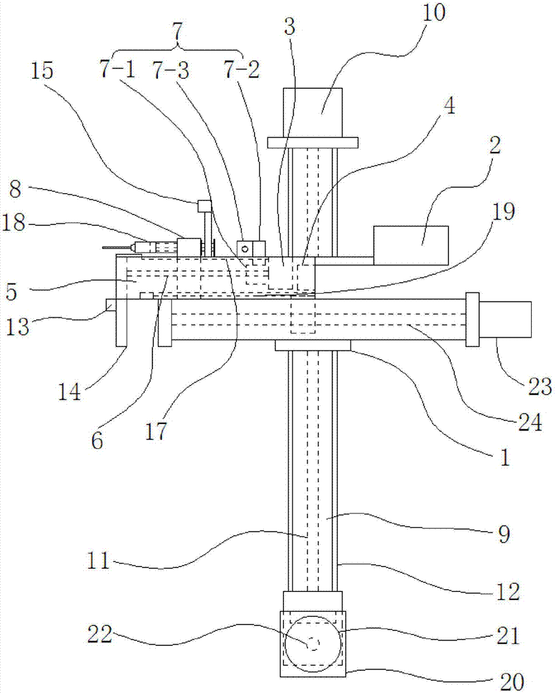
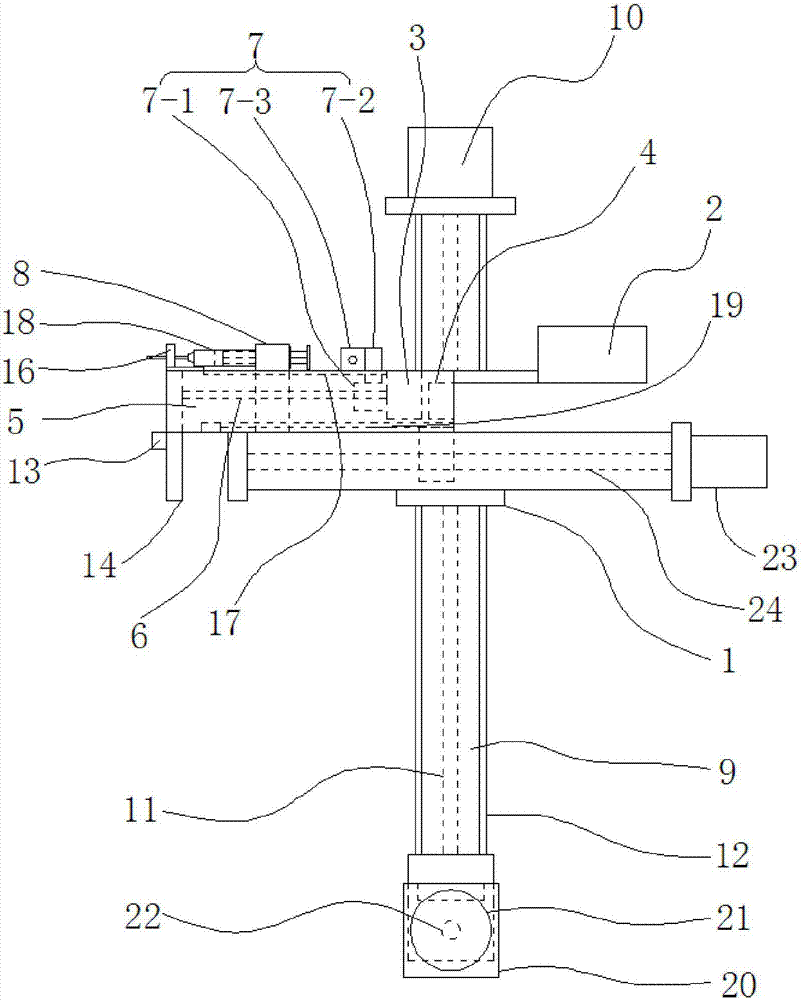
[0038] The principles and features of the present invention are described below in conjunction with the accompanying drawings, and the examples given are only used to explain the present invention, and are not intended to limit the scope of the present invention.

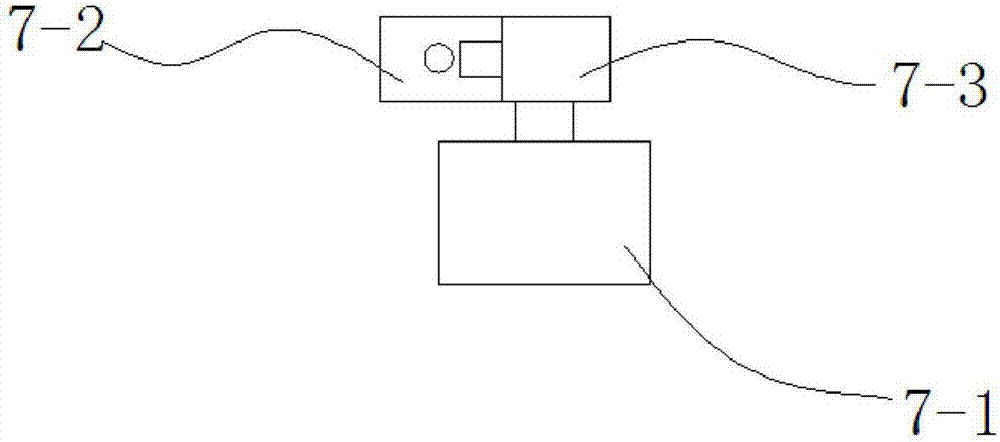
[0039] Such as figure 1 As shown, an embodiment of the present invention includes a bracket 1, a controller 2, a stepper motor A3 and an electromagnet 4, and the controller 2 is connected to the stepper motor A3 and the electromagnet 4 circuits respectively, Described carriage 1 is provided with slide table 5, and one end of described carriage 1 is fixedly provided with described stepper motor A3, and described carriage 1 is provided with screw mandrel A6, and the output end of described stepper motor A3 One end of the screw rod A6 is connected by transmission, and the screw rod A6 is provided with a syringe pushing part 7 for connecting the piston end of the syringe 18, and the stepper motor A3 drives the The scre...


PUM


Abstract

The invention relates to the technical field of medical devices, in particular to a fully-automatic painless injection device. The device comprises a bracket, a controller, a stepping motor A and an electromagnet, the controller is separately in electrical connection with the stepping motor A and the electromagnet, a sliding table is arranged on the bracket, the stepping motor A is fixedly arranged at one end of the sliding table, a lead screw A is arranged in the sliding table, the output end of the stepping motor A is in transmission connection with one end of the lead screw A, and an injector pushing part is arranged on the leas screw A; an injector clamping groove is formed in the sliding table; the electromagnet is arranged on the sliding table, and the electromagnet is driven by the controller to drive the injector clamping groove to move forth and back in the length direction of the sliding table. In the fully-automatic painless injection device, it is achieved that an injector quickly penetrates through the epidermis and hypodermic nerve endings through popup of the electromagnet, and the aim of relieving the pain is achieved; when the injector pashing part is precisely controlled through the stepping motor A and the lead screw A, the safety of injection is ensured, and the harm to a patient is reduced.

Description

technical field [0001] The invention relates to the technical field of medical equipment, in particular to a fully automatic painless injection device. Background technique [0002] Injection is an indispensable and important method in medical treatment. Whether it is body fluid sampling for case analysis or various drug injections for clinical treatment, injection is inseparable. However, the pain caused by the destruction and stimulation of the injected subcutaneous nerve tissue during the injection process will cause discomfort and rejection in the patient. At present, the painless injection technology based on reducing injection pain mainly consists of the following types: (1) epidermal drug delivery, such as microneedle array, needle-free injection and other technologies, the principle of pain relief of this technology is that the injection is only injected (high pressure jet) To the epidermal stratum corneum without nerve endings, and use the absorption of the stratum...

Claims


Application Information

Patent Timeline
Patent Type & Authority Applications(China)
IPC IPC(8): A61M5/20A61M5/46A61M5/42A61M5/31
CPCA61M5/20A61M5/31A61M5/427A61M5/46A61M2005/206A61M2005/2006A61M2209/082A61M2205/33A61M2205/18A61M2205/052Y02P70/10
Inventor 杨晓宇
Owner 重庆中电大宇卫星应用技术研究所有限公司
Why Eureka
Try Eureka