Self-aligning chamfering processing mode and equipment

A technology for automatic centering and processing equipment, which is applied in metal processing equipment, metal processing machinery parts, driving devices, etc., and can solve the problem of chamfering of shaft holes or workpiece ends and variable inner hole chamfering. Frequent tool replacement, affecting factory production efficiency and other issues, to achieve the effect of improving the single function, realizing multiple utilization, and avoiding the process of tool replacement

Active Publication Date: 2017-12-08
XIAMEN UNIV OF TECH
View PDF6 Cites 3 Cited by
  • Summary
  • Abstract
  • Description
  • Claims
  • Application Information

AI Technical Summary

Problems solved by technology

Obviously, the above two automatic chamfering machines can improve the efficiency and quality of chamfering processing, but neither of them can meet the processing requirements of different types of shaft holes or workpiece end round chamfering at the same time.
[0003]Taking the processing of inner hole chamfering as an example, most of the automatic chamfering machines on the market are one hole to one knife, that is, one model of hole corresponds to one For the chamfering of some variable inner

Method used


Image

  • Self-aligning chamfering processing mode and equipment
  • Self-aligning chamfering processing mode and equipment
  • Self-aligning chamfering processing mode and equipment

Examples


Embodiment 1

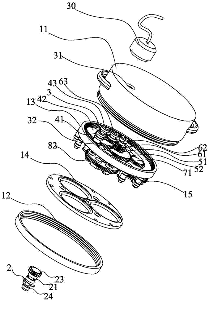
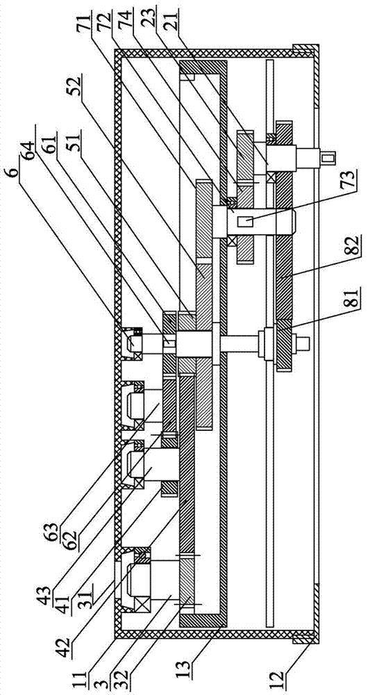
[0046] What the present invention discloses is an automatic centering chamfering processing equipment, such as Figure 1-2 As shown, it is a preferred embodiment of the present invention. The device includes a body, a power source 30, a cutter 2 and a transmission gear set, wherein the power source 30 can be a common pneumatic power source, and the cutter 2 is fixedly installed on the side of a cutter shaft 21. At one end, the cutter shaft 21 is rotatably installed on the transmission gear set, and the transmission gear set is assembled in the body. When the equipment is running, the cutter shaft 21 and the tool 2 can revolve around the center of the inner hole to be processed or the end surface of the workpiece with a variable revolution radius. , the power source 30 drives the cutter shaft 21 and the cutter 2 to rotate at high speed through the transmission gear set. The high-speed rotation of the tool 2 can realize the cutting of the port of the part, and its revolution aro...

Embodiment 2

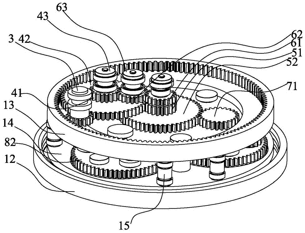
[0059] Further, in order to avoid changing the revolution radius of the tool due to the pressure of the workpiece or the edge of the inner hole on the tool when the tool is lowered, a ratchet mechanism can be provided between the box plate and the fixed plate, and the clockwise rotation of the planetary gear 82 relative to the central gear 81 can be prevented by the ratchet mechanism. Realize the locking of tool revolution radius.

[0060] Specifically, other structures of the device are the same as those in Embodiment 1, except that any planetary gear 82 is selected to set a ratchet mechanism, such as Figure 8 As shown, in order to ensure that the space distribution in the case is reasonable, the planetary gear 82 that the first gear 71 does not pass through is selected in this embodiment, and a ratchet 91 is fixed at the upper end of any fixed column 15 of the planetary gear, and the upper end of the first gear shaft 72 A ratchet 92 is fixed, and the ratchet 91 abuts agains...

Embodiment 3

[0063] The difference between this embodiment and embodiment two is only the position distribution of the pawls, such as Figure 9 In the present embodiment shown, a ratchet 91 is fixedly and movably installed on the fixed plate 14, because the fixed plate 14 is fixed below the box dish and rotates synchronously with the box dish, the ratchet 91 can also be selected to be fixedly installed on the bottom surface of the box dish. The pawl 91 can be installed in the gap on one side of the meshing part of the planetary gear 82. The pawl 91 can rotate around its installation shaft and reset by the coil spring or spring sleeved on the installation shaft. The claw tip of the pawl 91 is inserted at an acute angle. In the teeth of the planetary gear 82, when the planetary gear 82 moves counterclockwise relative to the wheel box under the drive of the central gear 81, the pawl 91 can rotate under the action of the gear teeth without affecting the progress of the planetary gear. When the ...


PUM


Abstract

The invention discloses self-aligning chamfering processing equipment and a corresponding processing mode. The self-aligning chamfering processing equipment comprises a main body, a power source, a cutter and a transmission gear set, wherein the cutter is fixedly mounted on one end of a cutter rotary shaft, the cutter rotary shaft is spinningly mounted on the transmission gear set, the transmission gear set is assembled in the main body, the power source drives the cutter rotary shaft and the cutter to rotate at high speed through the transmission gear set, and the cutter rotary shaft and the cutter can revolve around the center of an inner hole to be processed and the revolution radius is variable, a distance between the cutter of the equipment and the center of the inner hole to be processed can be adjusted automatically, so that the equipment can be better applied to the processing requirements of chamfering with different internal diameters, a cutter changing process is avoided and the production efficiency is improved.

Description

technical field [0001] The invention relates to a tool device for production in the field of mechanical processing, in particular to an automatic centering chamfering processing method and equipment. Background technique [0002] Chamfering is an inclined surface formed by grinding the end of the part or the edge of the inner hole in order to remove the burr generated by machining on the part and to facilitate the assembly of the part. In order to improve the efficiency of chamfering and to improve the quality and effect of chamfering, an automatic chamfering machine has emerged. Patent ZL201320462280.9 proposes an automatic chamfering equipment, which is equipped with a feed device, so that the drive spindle can automatically approach the part when it is running, and at the same time, the tool is driven by the connecting shaft and the gear set under the drive spindle to realize the rapid machining of chamfering; another patent application ZL201610785228.5 proposes to use a ...

Claims


Application Information

Patent Timeline
IPC IPC(8): B23D79/00B23Q5/06B23Q5/26B23Q1/26
CPCB23D79/00B23Q1/26B23Q5/06B23Q5/26
Inventor 李全城许昌超汪海林易吉祥陈锐刘飞
Owner XIAMEN UNIV OF TECH
Why Eureka
Try Eureka